

By
Shubham Sunil Malu
ABSTRACT
Suspension means to suspend something as system of spring and shock absorbers which supports vehicles on its wheels and make it more comfortable to write. In likely suspended bridge is a bridge which is suspended from cables running between the towers. We have discussed here how the bridge works and the force accounted in the bridge due to various load acting on it like wind, water, moving vehicles.
Here we discus the construction sequence in suspension bridge & have discussed the disaster in Tacoma narrow bridge in detail.
1.0 INTRODUCTION
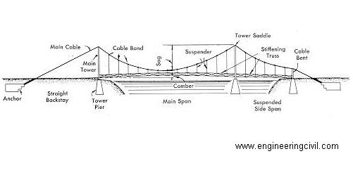
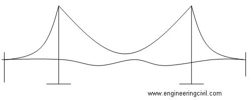
“Suspension bridge is one where cables or ropes or chains are stung across the obstacle & the deck is suspended from these cables”
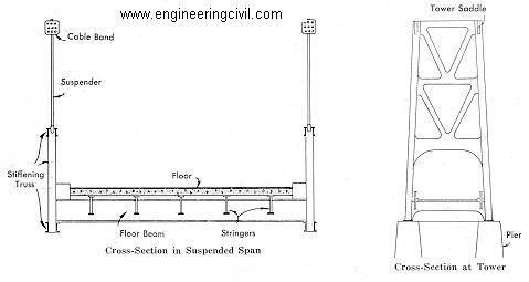
Anatomy of a Bridge
Deck – For pedestrian, train, and / or automobile traffic.
Supports – The towers are the supports.
Span – Describes the distance between towers.
Foundations – The supports rest on the foundations.
Approaches – The approaches are the roads leading up to the bridge.
Long wire cables – are strung over the towers and secured to the anchors on land.
Hangers – run from the cables to the deck hold it up.
2.0 HOW THEY WORK
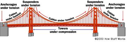
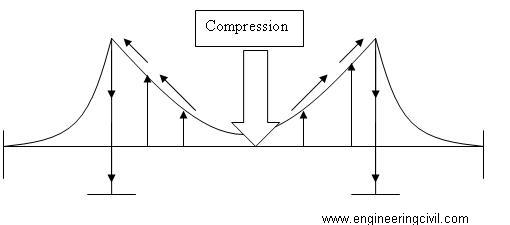
Any bridge can only stay up if it can support its own weight (called the dead load) and the weight of all the traffic that crosses it (called the live load). The load creates 2 major forces that act on parts of a bridge. The 2 forces are Compression and Tension:
2.1 Compression – The force of compression pushes down on the suspension bridge’s deck. but because its a suspended roadway, the cables transfer the compression to the towers, which dissipate the compression directly into the earth where they’re firmly entrenched.
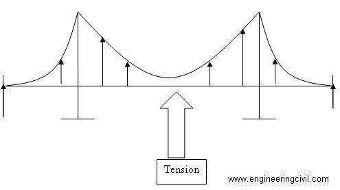
2.2 Tension – The supporting cables, running between 2 anchorages, are the lucky recipients of the tension forces. The cables are literally stretched from the weight of the bridge and its traffic as they run from anchorage to anchorage. The anchorages are also under tension, but since they, like the towers, are held firmly to the earth, the tension they experience is dissipated.
This is because the shape of the suspension bridge is actually one of the most stable structures there is. The cable of the bridge is inherently stable against any disturbance if it is thick enough to withstand any tension. The forces (tension mostly) are carried to the tops of the high towers (which should and usually are resilient against flexure, buckling, and oscillation) through the cables, instead of being directed towards the ground – which would happen if the bridge is an arch bridge. But what sets the suspension bridge apart from most conventional bridges is that all the forces do not “internally-cancel.” Instead, the forces are directed in a way that the tensions are resisted by the ground, which is in compression!
3.0 FORCES IN BRIDGE
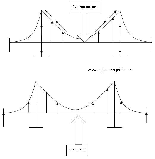
1. Compression :– the force of compression pushes down on the suspension bridge’s deck, but because it is a suspended roadway, the cables transfer the compression to the towers, which dissipates the compression directly into the earth where they are firmly entrenched
2. Tension:- The supporting cables, running between the two anchorages, receive the tension forces. The anchorages are also under tension but since they, like the towers, are held firmly to the earth, the tension they experience is dissipated . the cables and deck trusses are also under tension.
3. Dissipation:- The suspenders and cables avert the forces of tension and compression away from the roadway, to the towers and anchorages are firmly implanted into the ground the forces of compression and tension are dissipated into the ground.
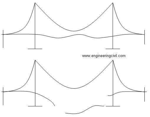
4. Torsion:- Torsion is a rotational or twisting forces . suspension bridges are very susceptible to torsion , especially in high winds. All suspension bridges have deck stiffening trusses, but in suspension bridges of extreme length, the deck truss alone is not enough. Wind tunnel tests are generally conducted on models to determine the bridges resistance to torsional movements. Aerodynamic trusses structures, diagonal suspender cables, and an exaggerated ratio between the depth of stiffening truss to the length of the span are some of the methods employed to mitigate the effects of torsion.
5. Resonance:- Resonance is a vibration in something caused by an external force that is in harmony with the natural vibrations of the original thing. Resonant vibration will travel through a bridge in the form of waves. In order to mitigate the resonance effect in a bridge, it is important to built dampeners into the bridge design in order to interrupt the resonant wave. If a bridge has, for example a solid road way , then a resonant wave can easily travel the length of the bridge. If a bridge roadway is made up of different sections that have overlapping plates, then the resonance cannot travel and build across the bridge, therefore minimizing the effect.
4.0 Construction sequence (wire strand cable type)
• Where the towers are founded on underwater piers, caissons are sunk and any soft bottom is excavated for a foundation. If the bedrock is too deep to be exposed by excavation or the sinking of a caisson, pilings are driven to the bedrock or into overlying hard soil, or a large concrete pad to distribute the weight over less resistant soil may be constructed, first preparing the surface with a bed of compacted gravel. (Such a pad footing can also accommodate the movements of an active earthquake fault, and this has been implemented on the foundations of the cable-stayed Rio-Antirio bridge. The foundation piers are then extended to above water level.
• Where the towers are founded on dry land, deep foundation excavation or pilings are used.
• From the tower foundation, towers of single or multiple columns are erected using concrete, stonework, or steel structures. At some elevation there must be a passage for the deck, with the columns extending high above this level.
• Smooth open cable paths called saddles are anchored atop the towers. These allow for slight movements of the cable as the loads change during construction. The top of these saddles may be closed with an additional part after completion of the bridge.
• Anchorages are constructed to resist the tension of the cables. These are usually anchored in good quality rock, but may consist of massive reinforced concrete deadweights within an excavation. The anchorage structure will have multiple protruding open eyebolts enclosed within a secure space.
• A temporary suspended walkway supported by wire rope follows the curve of the cables to be constructed, mathematically described as a catenary arc.
• Another set of wire ropes are suspended above the walkway and are used to support a traveler that has wheels riding atop these cables. There will be one set of wire ropes and a traveler for each cable to be “spun”
• Pulling cables attached to winches are capable of pulling the traveler from one anchorage to the other, traveling in arcs to the tops of the two towers.
• High strength wire, typically less than 10 mm in diameter, is pulled in a loop by pulleys on the traveler, with one end affixed at an anchorage. Workers stationed along the walkway attach the passing cable to a bundle with a temporary binding. When the traveler reaches the opposite anchorage the loop is placed over an open anchor eyebar.
• The traveler is returned to the start point to pick up another loop or it is used to carry a new loop from this side.
• As loops are placed, corrosion proofing may be applied.
• In this way a complete sub-cable is created linking the eyebar (or a set of eyebars) from one anchorage to the other. The sub-cables will have a hexagonal cross section and are held together with the temporary bindings.
• Multiple adjacent sub-cables are placed adjacent to each other. While these are on a hexagonal grid, the general form for the larger cable is circular.
• The entire cable is then compressed by a traveling hydraulic press into a closely packed cylinder and tightly wrapped with additional wire to form the final circular cross section.
• Saddles to carry the suspender cables are clamped to the main cables, each with an appropriate shape to conform to the ultimate slope of the main cables. Each saddle is an equal horizontal distance from the next, with spacing appropriate to the design of the deck.
• Suspender cables engineered and cut to precise lengths and carrying swedged ends are looped over the saddles. In some bridges, where the towers are close to or on the shore, the suspender cables may be applied only to the central span. Special lifting hosts attached to the suspenders or from the main cables are used to lift prefabricated sections of bridge deck to the proper level, provided that the local conditions allow the sections to be carried below the bridge by barge or other means, otherwise a traveling cantilever may be used to extend the deck one section at a time. If the addition of the deck structure extends from the towers the finished portions of the deck will pitch upward rather sharply, as there is no downward force in the center of the span. Upon completion of the deck the added load will pull the main cables into an arc mathematically described as a parabola, while the arc of the deck will be as the designer intended – usually a gentle upward arc for added clearance if over a shipping channel, or flat in other cases such as a span over a canyon.
• With completion of the primary structure various details such as lighting, handrails, finish painting and paving are added.
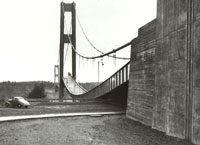
5.0 TACOMA DISASTER
• The Damage
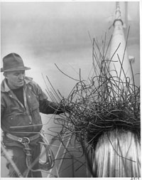
A bridge inspector checks the damaged cable WSDOT
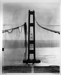
View of damaged cables and towers looking west, February 1943 WSDOT
1.0 Main cables: During the collapse, the main suspension cables were thrown violently side to side, twisted, and tossed 100 feet into the air & slipped from their positions in the cable saddles atop each tower.On the north cable at mid-span, where the cable band loosened, it broke more than 350 wires. Other wires were severely stressed and distorted.
2.0 Towers: Main towers including the bracing struts, were twisted and bent. Stress beyond the elastic limit of the metal resulted in buckling and permanent distortion.
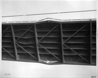
3.0 Deck-Floor System: Not surprisingly, the concrete and steel of the center span that now lay on the bottom of the Narrows was deemed a total loss. The remainder of the broken concrete on the side spans needed removal. The floor system had sections that were bent and overstressed.
4.0 Side Spans:
The loss of the center section, followed by the dropping of the side spans, caused substantial damage. The events stressed and distorted the plate girders and floor beams. Some buckled beyond repair.
5.0 Piers:
Both the West Pier (#4) and the East Pier (#5) sustained no damage. The collapse of the center span caused partial sheering of rivets that attached the towers to the tops of the piers.
6.0 Anchorages:
The anchorages for the main cables were undamaged. For building a replacement bridge, removal of part of the concrete would be necessary in order to spin the new main cables.
SUMMARY
1. In general, the 1940 Narrows Bridge had relatively little resistance to torsional (twisting) forces. That was because it had such a large depth-to-width ratio, 1 to 72. Gertie’s long, narrow, and shallow stiffening girder made the structure extremely flexible.
2. On the morning of November 7, 1940 shortly after 10 a.m., a critical event occurred. The cable band at mid-span on the north cable slipped. This allowed the cable to separate into two unequal segments. That contributed to the change from vertical (up-and-down) to torsional (twisting) movement of the bridge deck.
3. Also contributing to the torsional motion of the bridge deck was “vortex shedding.” In brief, vortex shedding occurred in the Narrows Bridge as follows:
(1) Wind separated as it struck the side of Galloping Gertie’s deck, the 8-foot solid plate girder. A small amount twisting occurred in the bridge deck, because even steel is elastic and changes form under high stress.
(2) The twisting bridge deck caused the wind flow separation to increase. This formed a vortex, or swirling wind force, which further lifted and twisted the deck.
(3) The deck structure resisted this lifting and twisting. It had a natural tendency to return to its previous position. As it returned, its speed and direction matched the lifting force. In other words, it moved ” in phase” with the vortex. Then, the wind reinforced that motion. This produced a “lock-on” event.
4. But, the external force of the wind alone was not sufficient to cause the severe twisting that led the Narrows Bridge to fail.
5. Now the deck movement went into “torsional flutter.”
“Torsional flutter” is a complex mechanism. “Flutter” is a self-induced harmonic vibration pattern. This instability can grow to very large vibrations.
Tacoma Narrows Failure Mechanism – original sketch contributed by Allan Larsen
When the bridge movement changed from vertical to torsional oscillation, the structure absorbed more wind energy. The bridge deck’s twisting motion began to control the wind vortex so the two were synchronized. The structure’s twisting movements became self-generating. In other words, the forces acting on the bridge were no longer caused by wind. The bridge deck’s own motion produced the forces. Engineers call this “self-excited” motion.
It was critical that the two types of instability, vortex shedding and torsional flutter, both occurred at relatively low wind speeds. Usually, vortex shedding occurs at relatively low wind speeds, like 25 to 35 mph, and torsional flutter at high wind speeds, like 100 mph. Because of Gertie’s design, and relatively weak resistance to torsional forces, from the vortex shedding instability the bridge went right into “torsional flutter.”
Now the bridge was beyond its natural ability to “damp out” the motion. Once the twisting movements began, they controlled the vortex forces. The torsional motion began small and built upon its own self-induced energy.
In other words, Galloping Gertie’s twisting induced more twisting, then greater and greater twisting.
This increased beyond the bridge structure’s strength to resist. Failure resulted.
5.0 CONCLUSION
As we discussed above the suspension bridge is the oldest form of bridge. Is one of the important type also. Here we had discussed how the bridge work and also the effect of forces developed in bridge. Hence while designing the “bridge forces analysis”, is the very important to make our structure stable, safe and sound.
Here we discussed , Taccoma Narrow Bridge – It is the best example of worst effect of natural calamities on bridge. Hence from study of above example we can conclude that while designing, analyses of bridge is very necessary from stability & safety point view.
6.0 REFERENCE
1.0 “Bridge Engineering” – S. P. Bindra.
2.0 “Road Railway Bridge & TUNNEL ENGINEERING” – G.S. Berde
3.0 “Bridge Engineering Hanbook”
4.0 http//www.google.com
We at engineeringcivil.com are thankful to Shubham Sunil Malu for submitting this very useful paper to us.
If you have a query, you can ask a question here.