Reasons behind thermal expansion and contraction in piping systems
One of the most powerful dynamic forces acting on piped services is thermal expansion and contraction. All piping materials expand or contract when pipes are exposed to higher or lower temperatures than the installation temperature. If a pipe run is fixed at both ends and heated, the expansion of the liner pipe due to temperature change will cause compressive stresses in the pipe material. If the resulting stress is strong enough to exceed the pipe material’s allowed stress, the pipe, supports, or piping components may be damaged. Depending on the extent of the damage, the facility may be forced to shut down for a period of time to make repairs or replace the piping system. Because piping systems frequently transport hot fluids, piping stresses and flexibility analysis must be carefully executed to minimize difficulties.
What are buttress dams?
A buttress dam consists of water retaining sloping membrane or deck on the upstream which is supported by a series of buttresses at right angles to the axis of the dam. The upstream water retaining sloping membrane may be in the form of a reinforced concrete slab or a series of arches or thickened buttress heads. At the upstream end a cutoff is provides to prevent or reduce the seepage of water.
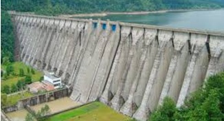
Buttress dams [1]
By
Shubham Malu
DEPARTMENT OF CIVIL ENGINEERING N.D.MV.P.S’s K.B.T.C.O.E NASHIK
1.INTRODUCTION
The artificial recharge to ground water aims at augmentation of ground water reservoir by modifying the natural movement of surface water utilizing suitable civil construction techniques. Artificial recharge techniques normally address to following issues –
(i) To enhance the sustainable yield in areas where over-development has depleted the aquifer
(ii) Conservation and storage of excess surface water for future requirements, since these requirements often changes within a season or a period.
(iii) To improve the quality of existing ground water through dilution.
(iv) To remove bacteriological and other impurities from sewage and waste water so that water is suitable for re-use.
Thus, in most situation, artificial recharge projects not only serve as water conservation mechanism but also assist in overcoming problem associated with overdraft.The increasing demand for water has increased awareness towards the use of artificial recharge to augment ground water supplies. Stated simply, artificial recharge is a process by which excess surface-water is directed into the ground – either by spreading on the surface, by using recharge wells, or by altering natural conditions to increase infiltration – to replenish an aquifer. It refers to the movement of water through man-made systems from the surface of the earth to underground water-bearing strata where it may be stored for future use. Artificial recharge (sometimes called planned recharge) is a way to store water underground in times of water surplus to meet demand in times of shortage.
Read More
By
Shubham Malu
DEPARTMENT OF CIVIL ENGINEERING N.D.MV.P.S’s K.B.T.C.O.E NASHIK
CHAPTER 1
1.1 INTRODUCTION
Rainwater harvesting is a technology used to collect, convey and store rain for later use from relatively clean surfaces such as a roof, land surface or rock catchment. The water is generally stored in a rainwater tank or directed to recharge groundwater. Rainwater infiltration is another aspect of rainwater harvesting playing an important role in storm water management and in the replenishment of the groundwater levels. Rainwater harvesting has been practiced for over 4,000 years throughout the world, traditionally in arid and semi-arid areas, and has provided drinking water, domestic water and water for livestock and small irrigation. Today, rainwater harvesting has gained much on significance as a modern, water-saving and simple technology.
The practice of collecting rainwater from rainfall events can be classified into two broad categories: land-based and roof-based. Land-based rainwater harvesting occurs when runoff from land surfaces is collected in furrow dikes, ponds, tanks and reservoirs. Roof-based rainwater harvesting refers to collecting rainwater runoff from roof surfaces which usually provides a much cleaner source of water that can be also used for drinking.
BY
S.P.Jadhav1, S.L.Ghorpade2, K.H.Bankar3, A.S.Adkar4, S.S.Kharade5
1Prof.Bansode S.S, 2Prof.Sawant P.A.
Department of Civil Engineering
S.B.Patil College of Engineering, Vangali, Indapur
Abstract-
The Rivers form a city’s lifeline and no other city in the country can boast of having three Rivers running through it. Karha riverfront in Baramati City is a multifunctional riverfront with majority of premises being used as Residential, Irrigation,Indusrial Recreational purposes.
The water quality of the Karha River is very low due to a large amount of untreated sewage being let into the river. Other major problem pertaining to Karha river is flooding of the river.
The project work aims to carrying out suitable river-training works and measures to reduce the river pollution, restore and maintain the river ecosystem as well as riparian ecosystem.
The aim of this project would be transform Baramati as a unique cultural platform with recreational and entertainment facilities serving the city.
Keywords– Riverfront,Pollution,Development,Ecological preservation,Public Space
By
Er. Vaishnav C R Nair
Introduction
The slabs are made depressed in depth form the general floor level in wet area like toilets, balconies, wash area in kitchen etc. This is to ensure the wet and dry area separations in buildings. Even though the sunken slabs provided the toilet and balcony areas are found with a major quality problem of Dampness. This is due to the continues contact of water with building blocks. Here comes the importance of Kerb Construction.
BY
Dr. Ukpong, E. C.
Civil Engineering Department, Faculty of engineering, University of Uyo, Nigeria
Abaraogu, Udechukwu John
Civil Engineering Department Faculty of Engineering University of Uyo, Nigeria.
ABSTRACT
Water quality analysis was conducted using the physical, chemical and biological analysis methods of water treatment for samples randomly selected from three (3) boreholes and three (3) hand dug wells in Uyo metropolis to determine their suitability for drinking in comparison of the WHO standards for drinking water. After the analysis, one (1) of the boreholes was found to be slightly acidic (pH 6.3) while others were within limit of WHO standards. The mean D.O for borehole (4.161mgl/l) were less than that of wells and did not meet the WHO limit. (5-14mg/l). The BOD of all samples did not satisfy the WHO limit of 2-4mg/l. lead concentrations in bored holes were slightly above WHO limits of 0.01mg/l. the concentration of ions (Fe4, Ca2+ and mg2+), sulphate, and Nitrate fell within the WHO limit. From analysis, it will be concluded that the different water sources are good sources of drinking water.
Read More
By
Prof. Madhuri K. Rathi, Mr. Patil Dhananjay Rajiv
Amrutvahini College of Engineering, Sangamner
Abstract
The concentration of the inlet wastewater of urban sewage treatment plants is much lower than the expected level in the design stage, mainly because of the problems of construction, management and maintenance of the drainage systems. Through investigation of the urban drainage pipelines, primary problems of drainage network damage, local unreasonable elevation design, pipe blockage and drainage system confusion, etc. were found. Combining the local actual situation, some corresponding engineering and management measures and some feasible suggestions for drainage pipe construction, management and maintenance are put forward.
Read More
To reduce the dead load and hence to reduce the settlement of pumping stations, the voids inside the raft foundations are filled with light material. If instead concrete is placed inside these voids, it poses severe thermal cracking problem and drastically increases loads to pumping stations. The use of general fill is also not desirable because its self-weight is comparable to that of concrete. On the contrary, if these voids are left vacant, water may penetrate into these voids during future operation and increases the dead load of pumping stations during its normal operation. Therefore, lightweight infill material, which is non-water-absorbing and non-biodegradable, is designed inside these voids to avoid ingress of water and to reduce the dead load of the structure.
This question is taken from book named – A Self Learning Manual – Mastering Different Fields of Civil Engineering Works (VC-Q-A-Method) by Vincent T. H. CHU.
In the construction of screw pump troughs, trapezoidal-shaped troughs are usually formed by using normal formwork. In order to enhance close contact between screw pumps and troughs, upon lifting the screw pumps into the troughs screeding works is carried out. Screw pumps are set to rotate and screeds are placed between the gap of screw pumps’ blade and trapezoidal-shaped troughs during the rotating action of screw pumps. After the screed sets, it serves to prevent leakage of water during the pumping operation of screw pumps.

This question is taken from book named – A Self Learning Manual – Mastering Different Fields of Civil Engineering Works (VC-Q-A-Method) by Vincent T. H. CHU.