

Introduction
Multi-storeyed Building
A multi storeyed Reinforced Cement Concrete Building is a combination of Concrete, reinforcement, Timber and lots of building material to form the various parts of the building like, Column, Beam, Slabs, Doors and Windows. All the components of the building are Rigid and forms a monolithic structure. It forms a continuous system which reduces the moment, transmits the load more evenly and forms a redundant structure. The load through the continuous system of beams and columns move to the foundation and later to the soil supporting to the structure.
The construction of a multi-storeyed building involves design and analysis of each and every part of the structure for the dead –live load, Seismic load and Wind load. There are various methods involve in this. The method usually used in calculating fixed end moment is Moment Distribution method and for seismic analysis method usually used is Portal method. A Building is a 3-dimensional structure with vertical columns and mutually perpendicular structure in 2 direction. These structures can be separated in two load transmission mechanism, viz. gravity load resisting and lateral load resisting. These both the system is complementary and interactive.
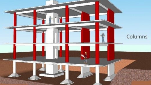
Fig 1: Multi-storeyed Building
Courtesy: Digital Civil
1. Loads
Any engineering structure in the world is a matrix of various elements of varying size, shape and Density. The densities of various elements with the volume provide a load to the structure called as Dead load of Self weight of the structure. Along with this there are various external loads that act on the structure. These are Live Loads, Seismic load, Wind load and Snow load. The structures need to be designed to withstand these loads during his life cycle and analysed for the safety of the structure and the residents.
1.1 Dead Load
This load is a static load that acts on the structure. It is primarily the weight of various components of the structure. It may be weight of fixed components of the structure or movable component.
It can be calculated by assigning the density of the materials of the member and multiplying with the volume of the member. This means that the dead load can be calculated very easily and accurately. Some of the common members of buildings and the corresponding densities are given below.
Table:1 Materials commonly in use in building and corresponding weight density.
| Sl. No | Material | Weight Density kN/m3 |
| 1 | Plain Concrete | 24 |
| 2 | Reinforced cement concrete | 25 |
| 3 | Brick Masonry | 18.8 |
| 4 | Stone Masonry | 20.4-26.5 |
| 5 | Timber | 5-8 |
| 6 | Bricks | 15.6-18.8 |
| 7 | Limestone | 23.5-26 |
| 8 | Sandstone | 22-23.5 |
| 9 | Steel | 77 |
| 10 | Sand | 17.3-19.6 |
| 11 | Water | 9.81 |
| 12 | Roof GI sheet | 0.049 |
1.2 Live Load
It is an imposed vertical load. These are temporary, changeable and dynamic. In a building this load arises because of the utilisation of the building by the occupants. Various movable partitions, objects used by occupants like Almirahs, Furniture etc. This load as movable it changes from time to time and hence it must be carefully selected by designer. It is one of the primary loads and designer generally use IS 875(Part-II) while assuming this load.

Figure 2: Live Loads Of Residential Building
Courtesy: Istock
1.3 Seismic Load
It is an environmental load that depends on the location (Soil type), Size, mode of construction of the building, duration and intensity of earthquake. India is divided into four Zones as Zone II, III, IV and V in ascending order of risk of occurrence of earthquake. The Seismic load is both vertical and horizontal but vertical force does not affect the structure more hence mostly the horizontal seismic load is considered for the design and analysis of the structure. In this project IS 1893 (Part II):2002 will be used.
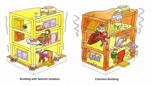
Fig 3: Earthquake effects in a building
Courtesy: Civil Digital
– Components Of RCC Building
Reinforced Cement concrete buildings consist of various parts which provide the strength to the structure to resist various loads coming into the structure. The loads on different floors of multi-storeyed RCC building are transferred from beams supporting the slab of the floor then to the columns which transmit it to the foundation. The substructure will be on a soil providing sufficient soil bearing pressure to provide equilibrium condition to the load coming onto it.
The various components of RCC building are:
Structural Components of RCC building
- Foundation
- Column
- Beam
- Slab
- Staircase
- Walls
- Doors & Windows
- Others
– Foundation
Foundation is the substructure that transmits the whole load of the superstructure to the soil on which it is resting. The soil must have enough bearing capacity to resist the load coming onto it. The load to be transmitted in such a way that it does not hamper the stability of the structure or the surrounding structures. The substructure needs to be properly analysed and designed considering the soil bearing pressure and lode coming into it. The construction of must safeguard the building from any physical damage that may come. The failure of the foundation takes place due to
- the movement of the soil fill
- the settlement of soil fill
Types
- Isolated Footing
- Combined footing
- Raft Footing
- Wall footing
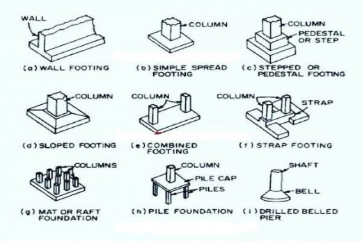
Fig 4: Types Of Footing
Courtesy: Pinterest
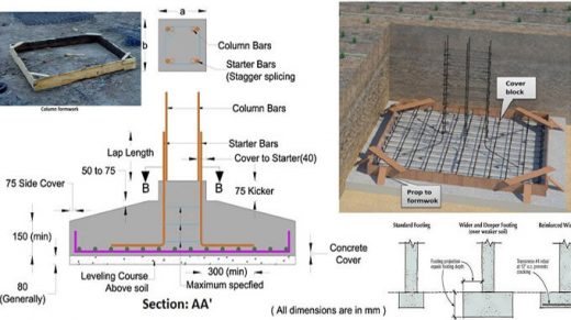
Fig 5: Parts Of Footing
Courtesy: Construction Costestimating
– Column
Columns are the vertical members in the structure where a load act axially on it. It takes all the load coming from the beam, slab, floor, wall and transmit it to the foundation. Column takes the load in compression but bending moment can takes place because of wind, earthquake and accidental load. The column should be placed in such a way that no tensile stress develops in any part of it. it must be partially or fully hide in the walls.
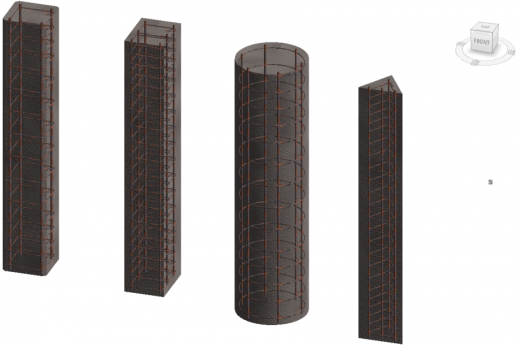
Fig 6: Types Of Column
Courtesy: Advantage.graitec
Column construction stages
- Column layout work
- Column Reinforcement Work
- Column Formwork
- Pouring Concrete
– Beam
Beams are normally placed horizontally. They resist bending when load is applied on them. The load acts on it laterally to the beam’s axis. It results in reaction forces at the point where the beam will get support. Generally, the support comes from the column. The combination of the external load and the reaction forces produces shear force and bending moment within the beam. This develops internal stress, strain and deflection of the body. The beam column connection is called direct support while beam to beam connection is called as the indirect support. The beams are classified based on manner of support, profile, length and their material.
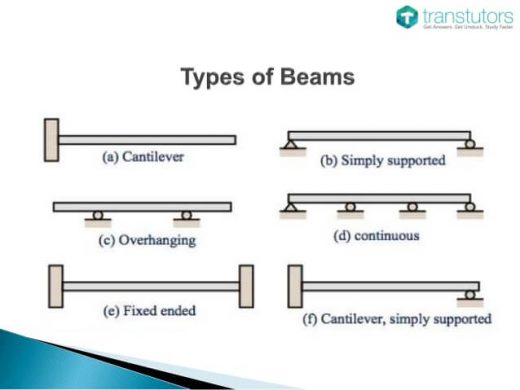
Fig 7: Types of beam
Courtesy: I am civil engineer
– Slab
RCC slabs is important part of building. It rests on beams and columns. Generally, slab has a thickness of 100 to 150 mm. As per IS 456: 2000, minimum slab thickness is 125 mm. The slab design is done by following ways
- Corrugated: Here, in a corrugated steel tray the concrete is poured which improves its strength and prevents the slab from bending by the virtue of its own weight. The corrugations run across the short dimension, from side to side.
- A ribbed slab: It gives extra strength on one direction.
- A waffle slab: It gives extra strength in both directions.
Reinforcement design
- A one-way slab has structural strength in shortest direction. It is supported on two sides.
- A two-way slab has structural strength in two directions. It is supported on all sides.
Fig 8: Slab In A Building
Courtesy: Hometips
– Walls
A wall is a structure that transfers loads to the beam and slabs above which it is constructed. It provides shelter and security to the people residing in the building. In RCC building brick work is done taking traditional burnt clay brick or concrete brick or engineering brick.

Fig 9: Burnt Brick Wall
Courtesy: Ancestryblogt Courtesy: 123rf

Fig 10: Concrete Brick Wall
Courtesy: 123rf
– Staircase
RCC stairs are commonly used in buildings because it can be easily moulded to any shape and is a better resilient to fire and wear. They are strong and aesthetic in appearance and longer span and width can be constructed easily. Various types of staircases are
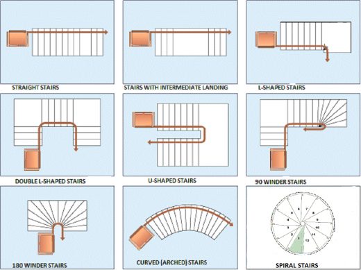
Fig 11: Types Of Staircase
Courtresy: Architecture Ideas
– Doors and Windows
Doors are provided for the entry and the exit to and from the structure. They are generally made up of timber but now a days it can be found in plastic too. Other options available are aluminium, steel, fibre, etc. Doors must be provided with adequate width and height for safe movement. Fire exit doors are also necessary in buildings to easy evacuation from the building during fire hazard. Windows need to be placed and sized in such a way that sufficient air movement to the building takes place and sunlight can reach inside the building.
-Others (Lintel and Chajja)
Lintel: It is a type of beam. These are provided above doors and windows to transmit the load coming from above wall to the side wall. The end of the lintel is supported by the masonry wall where it transmits the load. The width of the lintel is generally designed equally with the width of the wall.
Chajja: Chajja is projected small thickness slab over windows. These are projected to provide shade to the window also during rainfall it protects the wooden, iron structure of window from getting damaged and rusted respectively.
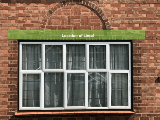
Fig 12: Lintel Location In A Building
Courtesy: Berrylodgesurveyors
Fig 13: Chajja Location In A Building
Courtesy: Autodesk Community
– Design Methodology
In the design of RCC structure there are three methods:
Working stress method: In the working stress method the permissible stress is apt far below the material strength. As far as load is concern the load assigned is the expected working load only. It is a traditional method of design and considers that the material will behave as linearly elastic manner. The factor of safety is the ratio of material strength to permissible stress.
However, the assumption that the stresses under working load is will be under the “permissible stress” does not takes place in reality as there are other factors like creep, shrinkages, effect of stress concentrations and other effects. The construction taking this method leads to huge sections which increases the economy.
Ultimate load method: This is an alternative method of working stress method. In this method the stress condition at the site condition of awaiting collapse of the structure is analysed. The load factor is the ratio of the ultimate load to the working load which is used for the design safety consideration of the structure. This generally marks in more slender sections, and often economical designs of structural members. However, the satisfactory ‘strength’ performance at ultimate loads does not guarantee satisfactory ‘serviceability’ performance at the normal service loads.
Limit State method: It is the combination of both the above method it satisfies the strength condition at the ultimate load and the serviceability at the working load. It considers various factors which provides adequate safety and serviceability to the structure. There are two types of limit state.
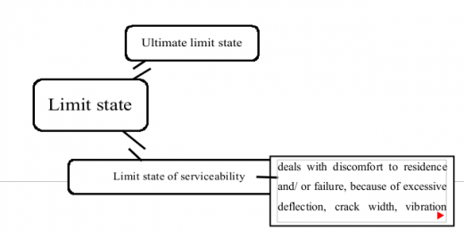
Fig 14: Limit state components
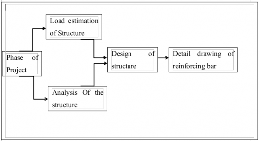
Fig 15: Phases of a general building project
If you have a query, you can ask a question here.