

INTRODUCTION
Footings are the bases laid on the soil on top of which a structure is erected. Thus, it is the foundation on which a building or any such structure stands upon. They are made of concrete having reinforcements inside them and are poured into an excavated ditch or conduit. Before the foundation is built, a test is done to assess the strength ofthe soil bearing capacity to ascertain the type of foundation to be built.
Given below are the types of footing and the situation under which they are applied is defined for better understanding-
1. Isolated Footing
2. Combined Footing
3. Raft Footing
4. Pile Footing
If the soil is soft or it is clay, then it cannot hold the structure if a strong foundation is not provided. In such a situation, the pile foundation is preferred. This is because the pile foundation transfers the load by the action of end bearing and skin friction. In case the soil is adequate in strength, then an isolated foundation is preferred. Generally, in residential buildings, isolated and combined footings are mostly preferred. If the distance between isolated footings is such that the ends touch each other or they overlap, then this implies that the distance between the column and the foundation is small. Hence, in such cases a combined footing is preferred as it makes the structure stable and economic. In other cases, if the soil is weak at shallow depth, then instead of a pile foundation, a raft foundation is built as it can distribute loads under the structure efficiently. Furthermore, the presence of secondary and primary beams tends to make the structure more stable in the raft foundation.
Here we have taken an example to depict how the calculations are done for an isolated footing. The column dimensions, grade of concrete and steel, design axial load, design bending moment of the structure, and soil bearing capacity are assumed. Also, we have assumed 75 mm brick flat soling as well as PCC with M 10 as the grade of concrete in PCC. In SBC, 25% is increased so that the footing can be designed for higher value. As the footing becomes safe for higher value of SBC then naturally it will be safe for any value lower than that.
The following are the steps as how the footing design is being proceeded-
1. Proportion of footing for column
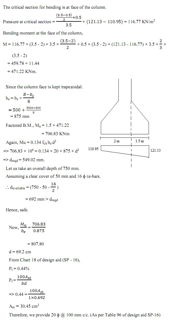
2. Check for bending moment
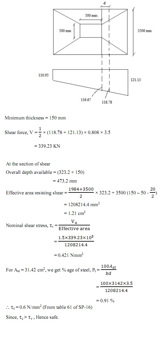
3. Check for one-way shear
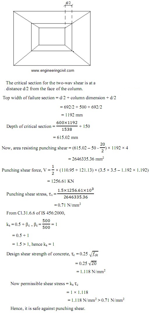
4. Check for two-way shear
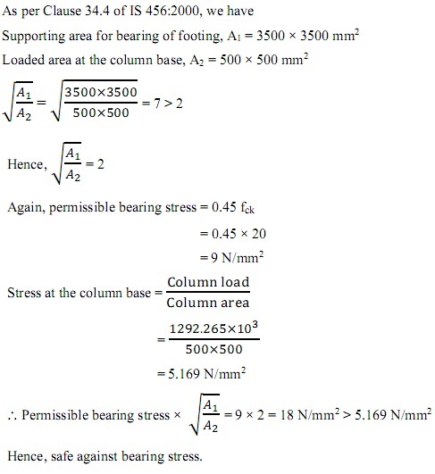
5. Check for bearing stress
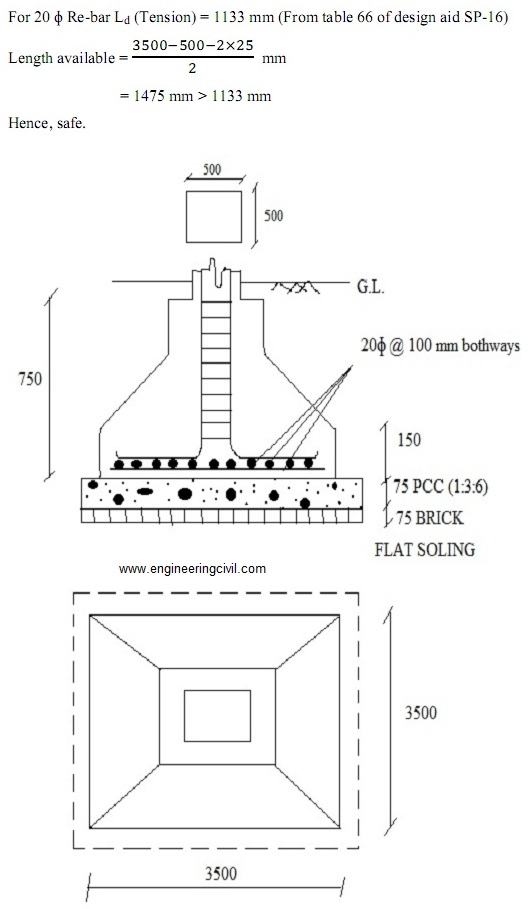
6. Check for development length
Finally, a detailed diagram has been shown for a clear vision of the footing design. If any information is missing, then it is assumed for a better calculative approach.
PROPORTIONING OF FOOTING FOR COLUMN:
Column B:
Maximum design axial load= 1292.265 KN
Design bending moment=109.095 KNm
Concrete mix= M20
Characteristic strength of reinforcement = 500 N/mm2
Size of column= 500 mm × 500 mm
Safe bearing capacity of soil=120 KN/m2(Assumed)
Increasing 25% we take S.B.C as 150 KN/m2
So, Given column axial load= 1292.265 KN
Add 10% for self-weight= 129.2 KN
Total= 1421.465 KN
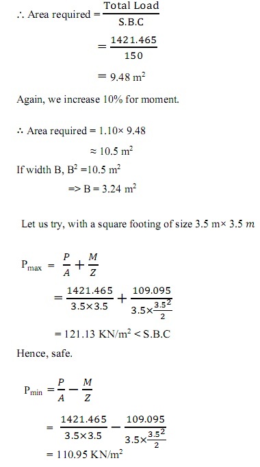
Check for Bending Moment:
Check for One-way shear
Check for two-way shear
Check for Bearing Stress
Check for Development Length
If you have a query, you can ask a question here.
I am very eager to learn
can you please explain one way shear check- at the section of shear over all depth calculation
it is better and clear analysis