

PAPER ON EFFECT OF ECCENTRICITY ON ANALYSIS & DESIGN OF ISOLATED FOOTINGS
(A CASE STUDY OF Jammu and Kashmir)
Note – Right click on images and click view image to see actual size of image
ABSTRACT
Footings are often subjected to moments from columns in addition to the axial loads. The presence of certain amount of eccentricity of loading in the footing induces moment on footing. A careful consideration has to be given to the presence of eccentricity, while performing the analysis and design of such footings, as an increase in eccentricity beyond certain limit renders a considerable area of footing ineffective to resist the stresses due to development of tension. Under these circumstances, the conventional flexural equation becomes inapplicable, thereby imparting more complexity in the analysis.
In this Thesis an attempt has been made to understand the behaviour of footings subjected to Uniaxial and biaxial eccentricity.
Two cases of uniaxial eccentricity are considered, Case I with column placed away from centre of footing, load being concentric with the column and Case II with column at centre of footing and load placed at certain eccentricity. For each case three conditions of eccentricity are considered ie e=0, eL/6. Complete analysis has been performed using Limit State Method for SBC = 40, 50, 65 and 100 KN/Sq m which are prevalent in the region under consideration. For biaxial cases two eccentricity conditions with eL/6 and SBC = 100 KN/Sq m have been analyzed. The analysis of footing subjected to biaxial eccentricity was carried out manually and as per charts and tables prevalent in literature.
A comparative study was conducted for both cases with reference to the design parameters and permissible values. The effect of eccentricity on quantity, cost and various other parameters were studied. The analysis was also carried out using SAP – 2000 Software for both Uniaxial and Biaxial Cases. The results obtained manually and by the use of software have been compared and difference analyzed. A computer program was developed for Analysis and Design of footing for Uniaxial and Biaxial cases in M.S. Excel to reduce the iterative work and to save time.
It was observed that there is a remarkable increase in quantity of concrete and steel when the loads are eccentric, the increasing factor being more in case of column placed away from the centre of footing as compared to the column placed at centre of footing. The results also highlight that the foundations become highly uneconomical if the geotechnical investigation reveals incorrect values of safe bearing capacities.
1.0 GENERAL
The foundation structure is designated as substructure as it is placed below the ground level and the superstructure is placed on the top of it. The elements of the superstructure transfer the loads and moments to its adjacent element below it and finally all loads and moments come to the foundation structure, which in turn, transfers them to the underlying soil or rock strata. Thus, the foundation structure effectively supports the superstructure. However, all types of soil get compressed significantly and cause the structure to settle. Accordingly, the major requirements of the design of foundation structures are the two as given below (Clause 34.1 of IS 456 – 2000):
1. Foundation structures should be able to sustain the applied loads, moments, forces and induced reactions without exceeding the safe bearing capacity of the soil.
2. The settlement of the structure should be as uniform as possible and it should be within the tolerable limits.
It is well known from the structural analysis that differential settlement of supports causes additional moments in statically indeterminate structures. Therefore, avoiding the differential settlement is considered as more important than maintaining uniform overall settlement of the structure.
In addition to the two major requirements mentioned above, the foundation structure should provide adequate safety for maintaining the stability of structure due to either overturning and/or sliding (Clause 20 of IS 456 – 2000). It is to be noted that this part of the structure is constructed at the first stage before other components (columns / beams etc.) are taken up. So, in a project, foundation design and details are completed before designs of other components are undertaken. However, it is worth mentioning that the design of foundation structures is somewhat different from the design of other elements of superstructure due to the reasons given below. Therefore, foundation structures need special attention of the designers.
1. Foundation structures undergo soil-structure interaction. Therefore, the behaviour of foundation structures depends on the properties of structural materials and soil.
2. Accurate estimations of all types of loads, moments and forces are needed for the present as well as for future expansion, if applicable. It is very important as the foundation structure, once completed, is difficult to strengthen in future.
3. Foundation structures, though remain underground involving very little architectural aesthetics, have to be housed within the property line which may cause additional forces and moments due to the eccentricity of foundation.
4. Foundation structures are in direct contact with the soil and may be affected due to harmful chemicals and minerals present in the soil and fluctuations of water table when it is very near to the foundation. Moreover, periodic inspection and maintenance are practically impossible for the foundation structures.
5. Foundation structures, while constructing, may affect the adjoining structure forming cracks to total collapse, particularly during the driving of piles etc.
2.0 SUMMARY OF LITERATURE REVIEW
1. In case of footings subjected to eccentric loading the design is more cumbersome, because the procedure of finding the reduced effective width and area of footing subjected to an eccentric load is time consuming.
2. Initially the eccentricity of the applied load needs to be calculated. It can be determined from the vertical load and the moment data available, but the basic purpose of design is to calculate the dimensions of the footing. The reduced effective dimension cannot be found directly.
3. Effective dimensions of the footing may be calculated by using the equation B = B -2eb
and L‘ = L-2eL
Where B = A/L
eb, eL = Eccentricities along width and length respectively
4. Method for calculating effective dimensions of eccentrically loaded footing using various derived formulae has been devised based on applicability of the combined direct stress and Flexural Formula that is the entire area must be in full compression for the application of the formula to be valid.
5. The dimensions of the footing may be calculated as 12 times the eccentricity of the given moments, Mx and My with the value of load. The maximum and minimum stresses are developed at the critical corners while the stresses at the other pair of diagonally opposite corners are equalized. This method can also be named as the 12 times eccentricity method of solution. This method is applicable when there are no space limitations on the dimensions a and b.
6. The maximum stresses in a rectangular footing subjected to vertical load eccentric about both the axis can be determined through a series of approximations based on Newton Raphson Method. It can be used for conventional calculations and may be programmed for high speed computing.
7. The standard bending equation q = P/A + P.ex. x /Iy + P.ey. y /Ix stands good for small eccentricities, when the footing area is in full compression, but it fails for bigger eccentricities when a part of the footing area does not stand fully on the soil.
8. The pressure settlement and pressure tilt characteristics of eccentrically obliquely loaded footings can be predicted using hyperbolic stress strain curve for soils.
9. Determination of bearing capacity of eccentrically obliquely loaded footing having rough base using concept of one sided failure can be analyzed in two parts:-
a) Bearing capacity of footing subjected to eccentric vertical load
b) Bearing capacity of footing subjected to central oblique load
10. The applicability of the combined direct stress and flexure formula, i.e., the whole footing area must be in full compression for the application of the formula to be valid. This condition is made possible by setting one corner of the rectangular footing with zero pressure and the diagonally opposite corner with the maximum allowable soil bearing pressure. By algebraic manipulations, the footing dimensions a and b are derived as functions of the vertical load, P, the maximum allowable bearing pressure fa, and the moments, Mx and My.
11. Minimum dimensions for the footing of eccentrically loaded foundations with different shapes in plan, can be determined by graphoanalytic means. It is based on the functional relationship of static and structural parameters (vertical forces, moments of forces, shape of the foundations’ footing, etc.), expressed in relative amounts, and can take into account the action of several combinations of loads in the calculation.
12. The complication of solving three simultaneous non linear equations for serviceability limit state analysis of biaxial bending can be avoided in all cases for which the following conditions are satisfied:-
I) The cross section is not prestressed.
II) The axial load is equal to zero.
III) The active concrete compression zone is triangular or trapezoidal.
IV) Shrinkage is neglected.
13 The coefficient of variability of only the angle of internal friction of soil has a significant effect on the failure probability of a eccentrically loaded footing.
14. In an eccentrically loaded footing various combinations of breadth and length offer themselves as solutions to the foundation problems within the ground pressures allowed. Where possible, an engineer should prefer a square footing to one that is long and narrow.
15. The tilt of footing increases with an increase in the eccentricity and the bearing capacity reduces considerably. Therefore, footing sizes increase and make the design uneconomical. Footing subjected to
uniaxial eccentric loads can be designed for no or negligible tilt by giving the footing an angle shape. The depth of footing projection will depend upon the eccentricity width ratio.
2.1 IDENTIFICATION OF GAPS
1. The studies carried out do not highlight the cases of Uniaxial Bending for various locations of the column with respect to the centre of footing.
2. The studies do not show a comparison of maximum soil pressure developed under eccentrically loaded footing as calculated by various methods for J&K region.
3. Analysis of eccentrically loaded footings using a software and comparison of results with the analytical solutions is missing.
4. No evaluation has been done for the effect of eccentricity on quantities, cost and other parameters for data pertaining to J&K.
5. Finite Element Modeling and analysis of footing with uniaxial and biaxial bending cases has not been carried out for the study area under consideration.
2.2 IMPORTANCE OF STUDY
1. The study will provide a comprehensive comparison of various parameters like area of footing, upward soil pressure, depth of footing, maximum bending moment etc for different eccentricity cases and various safe bearing capacities as prevalent in J&K.
2. It will highlight the effect of eccentricity on quantity and cost of concrete and steel with respect to the safe bearing capacities of soil in various regions.
3. Comparative graphs generated from this study can be helpful to the designers for the region under consideration.
4. The study will also provide graphical comparison of safe bearing capacities v/s gross, net and utilized areas of footing.
5. For the various safe bearing capacities of the study area, this study shall highlight the variation in maximum soil pressure developed as calculated by manual methods and using software.
6. The study will provide conclusions which will be helpful for the designers of the region to understand the effect of eccentricity on area of footing, net upward pressure, maximum bending moment, cost of footing etc.
2.3 SCOPE OF THE WORK
1. The thesis shall emphasize on the effect of eccentricity on various parameters related to Analysis and Design of Footing wrt the geotechnical data for J & K.
2. It will also deal with the determination and comparison of Maximum Soil Pressure under eccentrically loaded footing by various methods including analysis using SAP-2000.
3. The thesis shall also contain programs developed on M. S. Excel for analyzing uniaxial and biaxial bending cases.
4. A comparative study for both the cases shall be provided with reference to the design parameters and permissible values.
5. The study will also provide graphical comparison of safe bearing capacities v/s gross, net and utilized areas of footing.
6. The thesis shall also include a study on the effect of eccentricity on quantities, cost and other parameters.
2.4 OBJECTIVES OF THE WORK
The main objective of the thesis is to analyze and design the isolated footings for different cases involving uniaxial and Biaxial Bending. The analysis and design shall be carried out manually and with software. Comparative study shall be carried out for the generated results and evaluation of eccentricity on quantities, cost and other parameters worked out. Detailed objectives of the work are listed below:-
1. Analysis and Design of Isolated Footing with Uniaxial Bending using M. S. Excel Program: –
i. When Column is placed at center of Footing ie e = 0
ii. When Column is placed away from the center of Footing with eccentricity e<= L/6
iii. When Column is placed away from the center of Footing with eccentricity e >L/6
iv. When Column is placed at center of Footing with eccentricity e <= L/6
v. When Column is placed at center of Footing with eccentricity e > L/6
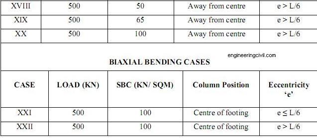
2. Analysis and Design of Isolated Footing with Biaxial Bending using M. S. Excel Program: -
i. When Column is placed at center of Footing with eccentricity e <= L/6
ii. When Column is placed at center of Footing with eccentricity e > L/6
3. Finite Element Method Modeling and analysis of Footing with uniaxial and biaxial bending using SAP – 2000
4. Determination of maximum soil pressure by manual calculation, by SAP-2000 and as per tables and charts prevalent in the literature
5. Comparative Study of generated results
6. Evaluation of effect of eccentricity on quantities, cost and other parameters.
7. Conclusions and Discussions
8. Limitations
3.0 METHODOLOGY
Following Methodology has been adopted for the thesis work: –
1. Study of various conditions which a footing has to satisfy while held in static equilibrium.
2. Identification of various cases of Uniaxial and Biaxial bending for analysis.
3. Identification of various Load & Safe Bearing Capacity Cases.
4. Use of Trial and Error solutions.
5. Use of charts and tables as prevalent in literature.
6. Development of Flowchart for determining preliminary size of footing subjected to vertical loads and moments.
7. Development of M. S. Excel Program for Design of footing.
8. Designing and detailing for each case.
9. Generation of Finite Element Method Model.
10. Carrying out F.E.M. Analysis.
11. Parametric study for different column positions, different Safe Bearing Pressures and varying eccentricity.
12. Study of effect of eccentricity on area of footing, concrete quantity, steel quantity, cost of concrete, cost of steel and percentage increase in overall cost.
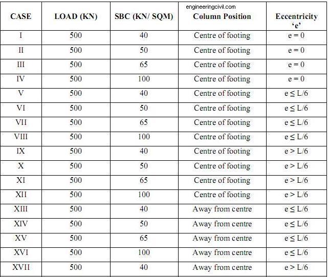
3.1 Following Load Cases and Safe Bearing Capacities have been considered for design of isolated footings:-
Based on the soil exploration report and various possible cases of Uniaxial and biaxial eccentricity cases as given in 3.1.2, following cases have been listed which shall be studied in this thesis. These cases include a combination of various values of safe bearing capacities and eccentricity ranging from 0 to greater than L/6. The cases shall be analyzed for two column positions ie Column at centre and column away from the centre of footing. For a comparison between the cases, load magnitude has been kept constant.
TABLE:-3.1 LOAD CASES
4.0 ABSTRACT OF ANALYSIS AND DESIGN
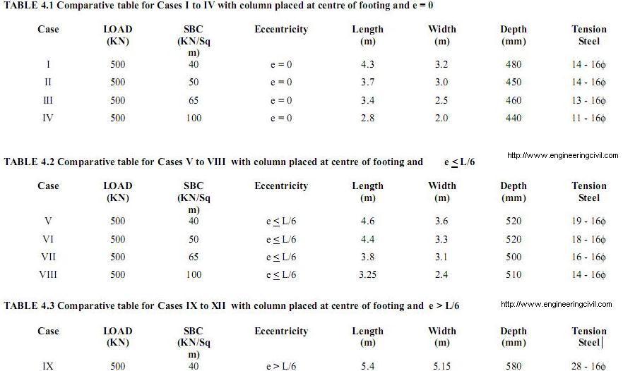
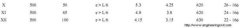
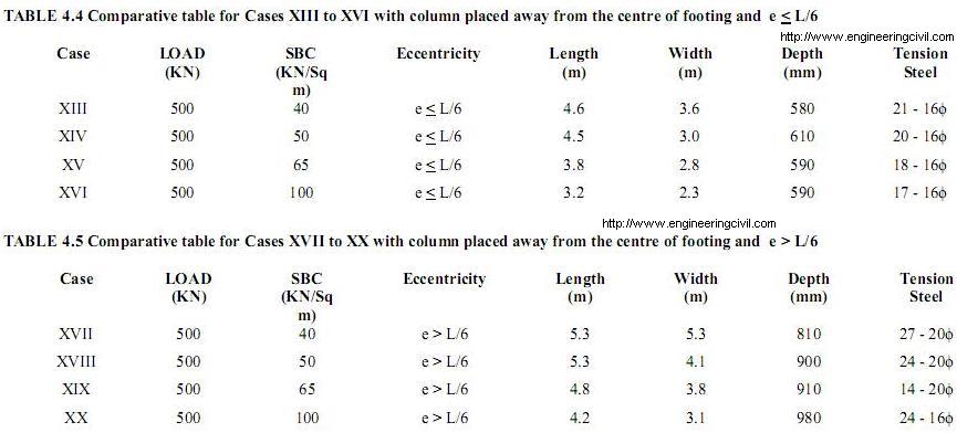
4.1 SUMMARY OF ANALYSIS AND DESIGN FOR CASES I TO XX
The analysis and design of footings for different cases are summarized below:-
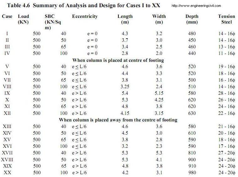
The above summary reveals that there is a remarkable increase in the dimensions and area of tension reinforcement required by the footing as the eccentricity increases from 0 to >L/6. Further for the same concentrated load and eccentricity condition, the dimensions required are more for lower safe bearing capacities. A comparative study of all the design features has been provided in chapter 6.
5.0 FINITE ELEMENT ANALYSIS
5.1 Graphical comparison of Manual and SAP-2000 Pressures
The variation of pressure as calculated manually and as obtained by SAP-2000is shown in chart 5.1below. Initially the pressure values are almost matching with each other but with an increase in length the manual calculations differ from the software calculations. The manual results are higher as compared to the software results.
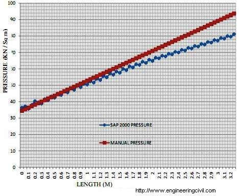
Chart No 5.1 Pressure Variations for Uniaxial Case, e < L/6
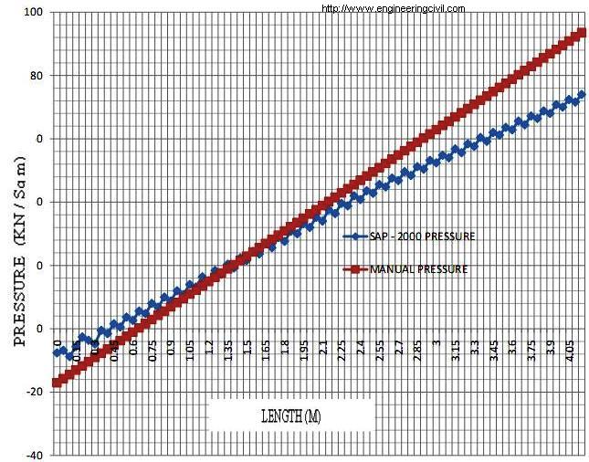
5.2 Graphical comparison of Manual and SAP-2000 Pressures
The variation of pressure as calculated manually and as obtained by SAP-2000is shown in chart5.2.. Initially the pressure values calculated manually are lower than that obtained by SAP – 2000.But with an increase in length the manual calculations are higher as compared to the software results.
5.3 Graphical comparison of SAP-2000 Pressures at different sections.
The variation of pressure calculated at five cross sections from one end to another is shown in chart 5.3. The pressure values are low at 0 length point and rise almost linearly towards the other end of footing. Moreover the pressure values also vary along the width of footing. Pressure values are higher at A line and go on reducing towards E line.
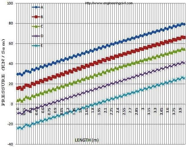
Chart No 5.3 Pressure Variations for Biaxial Case, e < L/6
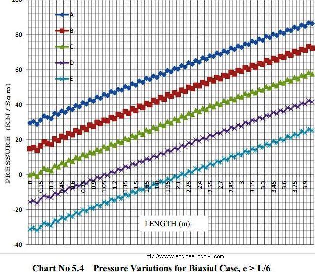
5.4 Graphical comparison of SAP-2000 Pressures at different sections.
The variation of pressure calculated at five cross sections from one end to another is shown in chart 5.4. The pressure values are low at 0 length point and rise almost linearly towards the other end of footing. Moreover the pressure values also vary along the width of footing. Pressure values are higher at A line and go on reducing towards E line.
6.0 RESULTS
6.1 GRAPHICAL COMPARISON OF ECCENTRICITY Vs COST WITH COLUMN AT e FROM CENTRE.
The variation of cost of footing with respect to the increase in eccentricity for different safe bearing capacity of soil is shown below. The curve shows that there is a slight increase in the cost of footing from eccentricity zero to less than L/6 beyond which there is a sharp increase in the footing cost when eccentricity increases to greater than L/6.
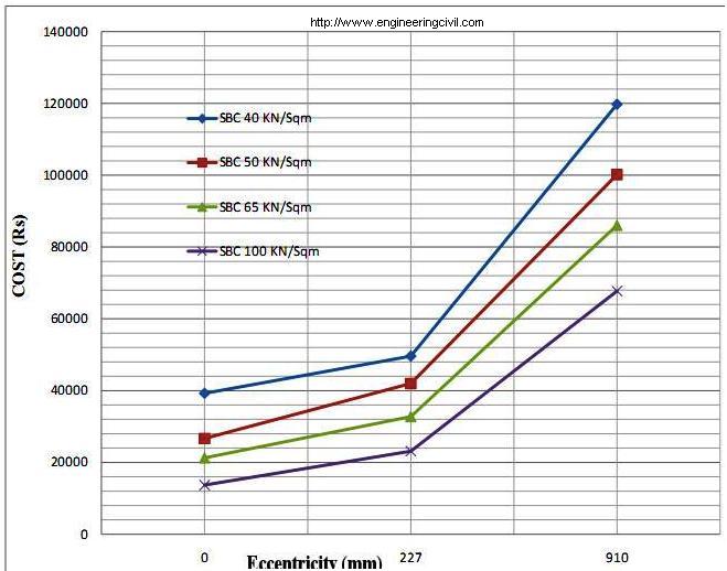
CHART 6.1 Eccentricity V/s Cost for Column at ‘e’ from centre, SBC = 40, 50, 65, 100 KN/Sqm
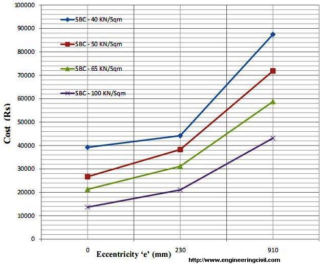
6.2 GRAPHICAL COMPARISON OF ECCENTRICITY Vs COST WITH COLUMN AT CENTRE.
The variation of cost of footing with respect to the increase in eccentricity for different safe bearing capacity of soil is shown in Chart 6.2. The curve shows that there is a slight increase in the cost of footing from eccentricity zero to less than L/6 beyond which there is a sharp increase in the footing cost when eccentricity increases to greater than L/6.
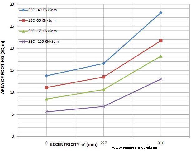
6.3 GRAPHICAL COMPARISON OF ECCENTRICITY Vs AREA WITH COLUMN AT e FROM CENTRE.
The variation of area of footing with respect to the increase in eccentricity for different safe bearing capacity of soil is given in Chart 6.3. The curve shows that there is a slight increase in the area of footing from eccentricity zero to less than L/6 beyond which there is a sharp increase in the footing area when eccentricity increases to greater than L/6.
6.4 GRAPHICAL COMPARISON OF ECCENTRICITY Vs AREA WITH COLUMN AT e FROM CENTRE.
A graphical comparison of Gross, Net and unutilized area of footing for different safe bearing capacities of soil is shown in Chart. It can be seen that the unutilized area is more for higher safe bearing capacities than lower ones.
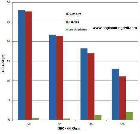
CHART 6.4 Gross / Net / Unutilized Area V/s Cost SBC = 40, 50, 65, 100 KN/Sq m
7.0 CONCLUSIONS
Following conclusions are drawn based on the cases considered in previous chapters:-
7.1 Uniaxial Eccentricity:-
7.1.1 Effect of Eccentricity on Area of Footing
1. With e = 227 mm (eL/6), the % increase in the area of footing over and above the case with e = 0 is around 104.14%, 95.77%, 114.6% and 132.5% for SBC = 40, 50, 65 and 100 KN/Sq m respectively.
7.1.2 Effect of Eccentricity on Net Upward Pressure
1. With e = 227 mm (eL/6), the % increase in net upward pressure over and above the case with e = 0 is around 4.43%, 8.9%, 4.86% and 4.45% for SBC = 40, 50, 65 and 100 KN/Sq m respectively.
7.1.3 Effect of Eccentricity on Maximum Bending Moment
7.1.3.1 Column placed at ‘e’ away from centre of footing
1. With e = 227 mm (eL/6), the % increase in maximum bending moment over and above the case with e = 0 is around 355.56%, 498.5%, 562.04% and 747.04% for SBC = 40, 50, 65 and 100 KN/Sq m respectively ie bending moment is increasing by 5.03 to 8.47 times.
7.1.3.2 Column placed at centre of footing
1. With e = 230 mm (eL/6), the % increase in maximum bending moment over and above the case with e = 0 is around 128%, 168.14%, 177.5% 219.82% for SBC = 40, 50, 65 and 100 KN/Sq m respectively ie bending moment is increasing by 2.7 to 3.2 times.
Thus by placing the column at centre of footing, the bending moment is reduced by 0.4 to 0.67 times for e=230 mm and by 2.75 to 5.27 times for e= 910 mm.
7.1.4 Effect of Eccentricity on Quantity of Concrete
7.1.4.1 Column placed at ‘e’ away from centre of footing
1. With e = 227 mm (eL/6), the % increase in quantity of concrete over and above the case with e = 0 is around 244.69%, 291.2%, 324.55% and 418.7% for SBC = 40, 50, 65 and 100 KN/Sq m respectively ie quantity of concrete is increasing by 3.45 to 5.18 times.
7.1.4.2 Column placed at centre of footing
1. With e = 230 mm (eL/6), the % increase in quantity of concrete over and above the case with e = 0 is around 144.24%, 179.4%, 189.25% and 234.55% for SBC = 40, 50, 65 and 100 KN/Sq m respectively ie quantity of concrete is increasing by 2.44 to 3.34 times.
Thus by placing the column at centre of footing, the quantity of concrete is reduced by 15% for e=230 mm and by 100.45% to 184.15 % for e=910 mm.
7.1.5 Effect of Eccentricity on Quantity of Steel
7.1.5.1 Column placed at ‘e’ away from centre of footing
1. With e = 250 mm (eL/6), the % increase in quantity of steel over and above the case with e = 0 is around 132.8%, 234.72%, 256.21% and 342.31% for SBC = 40, 50, 65 and 100 KN/Sq m respectively ie quantity of steel is increasing by 2.33 to 4.42 times.
7.1.5.2 Column placed at centre of footing
1. With e = 250 mm (eL/6), the % increase in quantity of steel over and above the case with e = 0 is around 37%, 143.1%, 144.65% and 172.03 % for SBC = 40, 50, 65 and 100 KN/Sq m respectively ie quantity of steel is increasing by 1.84 to 2.72 times.
Thus by placing the column at centre of footing, the quantity of steel is reduced by 0% to 17 % for e=230 mm and by 57% to 95.8 % for e=910 mm.
7.1.6 Effect of Eccentricity on Cost of Footing
7.1.6.1 Column placed at ‘e’ away from centre of footing
1. With e = 227 mm (eL/6), the % increase in cost of footing over and above the case with e = 0 is around 205.3%, 275%, 304.58% and 395.2% for SBC = 40, 50, 65 and 100 KN/Sq m respectively.
7.1.6.2 Column placed at centre of footing
1. With e = 230 mm (eL/6), the % increase in cost of footing over and above the case with e = 0 is around 122.92%, 169.3%, 176.22% and 215.32% for SBC = 40, 50, 65 and 100 KN/Sq m respectively.
Thus by placing the column at centre of footing is more economical as the increase in cost is around 13.78 to 15.31 % in case of e = 230 mm and around 82.38 to 180 % in case of e = 910 mm over and above when column is placed at ‘e’ away from the centre of footing.
7.2 Biaxial Eccentricity:-
1. It is observed that a small amount of biaxial eccentricity (0.73 m) which falls in the category of e > L/6 results in huge soil pressure 192.64 KN/Sq m which is approximately 2 times the safe bearing capacity of soil.
2. The manual procedure is quite rigorous and iterative in nature and takes a lot of time to arrive at the maximum soil pressure under the footing. The procedure can be simplified by using the standard charts and graphs prevalent in literature.
7.3 Comparison of Maximum Soil Pressure calculated by various methods
7.3.1 Uniaxial Case
The results obtained by hand calculations, as per chart given by ‘Teng’ and as per table given by ‘Fintel’ are in close confirmity. The variation is around 10 %. But the SAP-2000 results show a variation of 18 % which are lower than hand calculations.
7.3.2 Biaxial Case
The results obtained by hand calculations, as per chart given by ‘Teng’ and as per table given by ‘Fintel’ are in close vicinity. The variation is less than 6 %. But the SAP-2000 results show a variation of 26 % which are lower than other methods.
7.4 DISCUSSION
Thus the presence of eccentricity needs a careful consideration while designing the foundation of any structure. The presence of small eccentricity not only results in development of enormous compressive stress at one end which are much more than the safe bearing capacity of soil, but it also develops tensile stresses in the footing which ultimately renders a part of the footing area ineffective due to reduction in effective length and width of footing, thereby further aggravating the maximum soil pressure. This results in failure of the soil under the footing, tilting and failure of footings and ultimately failure of structure. Also the placement of column plays an important role in economy. Placing the column at centre of footing is more economical as the increase in cost is around 13.78% to 15.31 % in case of e L/6 over and above when column is placed at ‘e’ away from the centre of footing.
7.5 LIMITATIONS & FUTURE SCOPE
1. Analysis with/without tension/uplift at base.
2. Effect of depth and over-burden weight of soil.
3. Differences between footings for braced and un-braced frames/columns.
4. Effects of ground-beams to assist in resisting moments due to eccentricity.
REFERENCES
1 Brendum T and Nielsen ‘Concrete Sections under Biaxial Bending’- Journal of Structural Engineering, No 10, October 1987.
2 Davies G and Mayfield B ‘Choosing Plan Dimension for an Eccentrically Loaded Footing Slab’- American Concrete Institute Journal, Vol 69, No 5 – 1972.
3 Gurfinkel G, ‘Analysis of Footing subjected to Biaxial Bending’- Journal of Structural Division, Proceedings of the American Society of Civil Engineers, Vol 96, No ST6, June 1970.
4 Higleter W. H and Anders J. C, ‘Dimensioning of Footings subjected to Eccentric Loads’- Journal of Geotechnical Engineering, Vol III, No 5, May 1985
5 Holmberg A, ‘Discussion on Dimensioning Footings subjected to Eccentric Loads’- Journal of Geotechnical Engineering, Vol 14, June 1987
6 Irles R and Irles F, ‘Explicit stresses under Rectangular Footings’- Journal of Geotechnical Engineering, Vol 120, No 2, February 1994.
7 Jarquio R and Jarquio V, ‘Design of Footing Area with Biaxial Bending’- Journal of Geotechnical Engineering, Vol 109, No 10, October 1983.
8 Mahiyar H and Patel A. N ‘Analysis of Angle shaped footing under eccentric loading’, Journal of Geotech and Geoenvironment Engg. Volume 126, Issue 12, pp. 1151-1156 (December 2000)
9 Prakash S, Saran S and Sharan U.N, ‘Footings and Consecutive Laws’- Journal of Geotechnical Engineering, Vol 110, No 10, October 1984.
10 Plevkov V. S and Polishchuk A. I ‘Assigning Dimensions of the Footing of Eccentrically Loaded Foundations’- Journal of Soil Mechanics and Foundation Engineering, Publisher:- SPRINGER, New York, Vol 30, No 05, September 1993.
11 Saran S and Agarwal R.K, ‘Eccentrically – Obliquely Loaded Footing’- Journal of Geotechnical Engineering, Vol 115, No 11, November 1989.
12 Saran S. and Agarwal R.K, ‘Bearing Capacity of Eccentrically – Obliquely Loaded Footing’- Journal of Geotechnical Engineering, Vol 117, No 11, November 1991.
13 Smith J. P, Pardo and Bobet A , “ Behavior of Rigid Footings on Gravel under Axial Load and Moment “ Journal of Geotechnical and Geoenvironmental Engg, Volume 133, Issue 10, October 2007.
14 Soubra A. H. ‘Reliability based Analysis and Design of Eccentrically Loaded Footings’- Journal of Geotechnical Engineering, Vol 336, No 49- 2009.
15 Wilson K. E. ‘Bearing Pressure for Rectangular Footings with Biaxial Uplift’, Journal of Bridge Engg. Volume 2, Issue 1, pp. 27-33 (February 1997)
16 Bowles J.E, ‘Foundation Analysis and Design’, Mc Graw Hill Book Company, New York, London, Mexico, Sydney, Tokyo.
17 Fintel M, ‘ Handbook of Concrete Engineering’, C.B.S Publishers and Distributors, New Delhi.
18 Jain A.K, ‘ Limit State Design’,
19 Kurian N.P, ‘Design of Foundation Systems’, Narosas Publishing House, New Delhi.
20 Teng W.C, ‘Foundation Design’, Prentice Hall of India (Pvt) Ltd, New Delhi.
21 Tomlinson M. J, ‘Foundation Design and Construction’, Longman Singapore Publishers Ltd, Singapore.
22 I.S 456 – 2000, Code of Practice for Plain and Reinforced Concrete.
23 I.S 6403 – 1981, Code of Practice for Bearing Capacity of Shallow Foundation.
We at engineeringcivil.com are thankful to Sir Sajad Ahmed Khan, Lecturer – I Department of Civil Engineering Government Polytechnic, Leh – Ladakh and Dr Hemant Sood, Associate Professor NITTTR, Chandigarh for submitting this research paper to us. We hope this will be of great use to many civil engineering students around the world.
If you have a query, you can ask a question here.
Nice work done. Can be further used to see the variations wrt different loads.
gud work
1. The % increase in quantity of concrete over and above the case with e = 0 is around 244.69%, 291.2%, 324.55% and 418.7% for SBC = 40, 50, 65 and 100 KN/Sq m respectively,
2.The % increase in quantity of concrete over and above the case with e = 0 is around 144.24%, 179.4%, 189.25% and 234.55% for SBC = 40, 50, 65 and 100 KN/Sq m respectively.
The above two statements are conflict,
Usually, when the SBC is higher – % of cost for foundation would be lesser.
Need other experts views on it….
Regards.
Er. S. Thirumarainathan..
Informative. Thankyou. 🙂