

By
Laxmanagouda
GEC HUVINA HADAGALI
CHAPTER 1
INTRODUCTION
1.1 GENERAL
The various underground construction methods discussed as options for the example facility must be evaluated on a site-specific basis, since factors such as site geology will vary significantly in different locales. The advantages and disadvantages of each option must be weighed, and each alternative’s costs and energy use must -be evaluated. The most effective options can .then be considered in terms of the various constraints posed by the individual site.
The article summarizes the challenges and considerations during planning, execution and commissioning of underground sections of metro. The work of fixing the alignment starts with fixing up the location of the station box, availability of the land in the close proximity of major origin/destination points or nodes which are dense passenger traffic junction is important. There are the instances when separate vacant land at these locations is not available, and in all such cases stations are planned below roads. Consideration of buildings nearby, no. of trees affected, possible traffic diversion, soil strata, utilities, access to the residents nearby are few points which are kept in mind the location of the station. Suitability from point of view of traffic integration is also a main criterion for fixing station locations. Stations are planned in such a way so as to be near established traffic interchange nodes so that they fit in the existing transport network and provide seamless intermodal transfer.
Underground construction has been around for thousands of years, mostly developed through mining and more recently through transport, housing and commercial industries. The Channel Tunnel, London Underground, British Library, and various shopping centre are all examples of underground construction. Underground housing (sometimes called earth sheltered housing) refers specifically to homes that have been built underground, either partially or completely. These subterranean homes have grown increasingly popular over the last thirty years and are an important sector in the green building movement.
Thousands of people in Europe and America live in underground homes. In Russia there is more development below the ground than above it. Countries like Japan and China, where development space is at a premium, are particularly keen to build underground living places. In the UK, the movement is much slower, with less than a hundred underground homes in existence. This is partly due to a misinformed belief that underground homes are dirty, damp, dark, claustrophobic and unstable places to live. But it is also due to a lack of guidance and information about building regulations and specifications, and a lack of knowledge about their potential as a sustainable building practice.
A tunnel is an underground passageway, completely enclosed except for openings for egress, commonly at each end. A tunnel may be for foot or vehicular road traffic, for rail traffic, or for a canal. Some tunnels are aqueducts to supply water for consumption or for hydroelectric stations or are sewers. Other uses include routing power or telecommunication cables, some are to permit wildlife such as European badgers to cross highways. Secret tunnels have given entrance to or escape from an area, such as the Cu Chi Tunnels or the smuggling tunnels in the Gaza Strip which connect it to Egypt. Some tunnels are not for transport at all but rather, are fortifications, for example Mittelwerk and Cheyenne Mountain.
In the United Kingdom, a pedestrian tunnel or other underpass beneath a road is called a underpass subway. In the United States that term now means an underground rapid transit system. The central part of a rapid transit network is usually built in tunnels. Rail station platforms may be connected by pedestrian tunnels or by foot bridges.
The construction of underground tunnels, shafts, chambers, and passageways are essential yet dangerous activities. Working under reduced light conditions, difficult or limited access and egress, with the potential for exposure to air contaminants and the hazards of fire and explosion, underground construction workers face many dangers. To help employers protect the safety and health of underground construction workers, the Occupational Safety and Health Administration (OSHA) has prepared a number of guidance documents, including the underground construction regulations, found in Part 1926, section 800 of Title 29 of the Code of Federal Regulations (29 CFR 1926.800).
1.2 OBJECTIVE
The’ objective of this study was to obtain information on the costs, energy considerations, and security and survivability potential provided by current underground construction technology.
1.3 APPROACH
Computer literature searches were performed to obtain information on underground buildings and construction practices. Current procedures and problems in underground construction were evaluated in the areas, of cut and cover methods, deep shafts, tunneling, ground water control, security and survivability, costs, and energy savings. An example facility was then considered for various forms of underground construction (cut and cover, deep shaft,’ and tunneling) to illustrate application ‘of the information Obtained. Mode of Technology Transfer It
CHAPTER 2
UNERGROUND CONSTRUCTION METHODS
2.1 GENERAL
The underground construction standard covers many topics of concern to those who work in the challenging environment of underground construction. A sampling of items covered by the standard includes requirements for safe access and egress routes, employee training in hazard recognition, a “check-in or check-out” procedure, and emergency procedures. This booklet summarizes all requirements of the standard. The standard provides some flexibility in methods to control workplace hazards in underground construction as long as appropriate precautions are taken to protect workers in a variety of situations. OSHA requires that a “competent person” be responsible for carrying out several requirements of the underground construction regulations. Situations that require intervention by a “competent person” are identified in the following sections.
2.2 TRAINING REQUIREMENTS
All employees involved in underground construction must be trained to recognize and respond to hazards associated with this type of work. Training should be tailored to the specific requirements of the jobsite and include any unique issues or requirements.
The following topics should be part of an underground construction employee training program:
• Air monitoring and ventilation
• Illumination
• Communications
• Flood control
• Personal protective equipment
• Emergency procedures, including evacuation plans
• Check-in/check-out procedures
• Explosives
• Fire prevention and protection
• Mechanical equipment
2.3 CONSTRUCTION METHODS
Useful references on underground construction technology were identified from journals and government reports. Report subjects included methods of excavation, tunneling, underground structure lining, waterproofing practices, security, survivability, and cost and energy considerations. Much of the literature presented application of different construction methods to specific structures, such as civil’ defense shelters, subways, tunnels, schools, and libraries.
The papers surveyed discuss underground construction methods used in the United States and 11 other countries.. Each article is designated by country and reference number. This reference number corresponds to the complete list of references found in the appendix. Many other type of construction methods listed below
I. Cut –and –cover method
II. Wall-cover construction method
III. Conventional underground tunneling
IV. Machine driving
V. Open cut methods
VI. Underground driving methods
VII. Immersed tube method
VIII. Box jacking
CHAPTER 3
METHODOLOGY
3.1 GENERAL
Many Department of Defense hardened structures such as those found at munitions storage facilities are constructed above ground, some with earth cover. An example of such a structure is the standard storage igloo. These facilities are often quite old, and the set of requirements on which they were designed and built differ from those considered important today. These facilities were based mainly on safety, with less attention given to security, Survivability, and operational and environmental considerations. In Europe, where security and survivability are important in facility design and construction, many NATO military facilities are built either underground or in the sides of mountains. Many of the installations are tunneled into rock in the mountainsides which is relatively fault-free and is not prone to flooding during construction., Often, the rock is so strong that the tunnel walls do not have to be lined. The Scandinavian countries have built many underground or mountainside structures for civil defense. The mountainous terrain provides a very hardened personnel shelter compared to what could be built above ground. In the United States, under the direction of the Federal Emergency Management Agency, much work, including a great deal by the Corps of Engineers, has been done recently to design underground or earth-covered key worker shelters. The earth covering provides both over pressure hardening and radiation and thermal protection. Several options are available for hardened facility construction. Typically, above ground structures are made of thick reinforced concrete and can provide only limited protection. The structure can be shallow-buried, using the cut and cover construction method. This removes the structure from the surface, so it is not directly exposed to threats; however, it is still vulnerable to penetrating weapons and bombs. Tunneling, down.(shaft) or into mountainsides can provide a very safe environment, but multiple entrances must be provided. Also, the local geology is an important factor. Deep excavation, another option, which has excellent security and survivability potential, but which requires multiple entrances. Problems encountered with deep excavations include shoring, water table, and bedrock level.
Cut and cover method
Cut and cover is the most commonly used underground, construction method. This is essentially an open excavation in which the structure is supported by retaining walls while it is built and then backfill placed above the completed facility. Raja gopalan provides an excellent discussion of the basis for designing a cut and cover excavation His paper cites extensive use of the cut and cover technique -for underground railway construction n India. Structures butt d at relatively shallow depths are generally well suited for cut and cover techniques, off ring a fairly low-cost. excavation approach . The major drawback of cut and cover meth Ids is the large work area it required. The designer must’ make a decision based not only on construction costs, but also on the relative merits of other types of construction, such as tunneling , which are greatly reduce surface traffic interference. Conventionally braced excavation support systems consist of a web of walkers, rakers, posts, and lateral support lacing. The walker is a horizontal member used to support formwork stds and a raker is a sloping area. A major problem with this system is that the support structure often conflicts with the excavation and placement of the permanent structure Excavations which use tieback.
Box jacking method
Box jacking is similar to pipe jacking, but instead of jacking tubes, a box shaped tunnel is used. Jacked boxes can be a much larger span than a pipe jack with the span of some box jacks in excess of 20m. A cutting head is normally used at the front of the box being jacked and excavation is normally by excavator from within the box.
Pipe jacking method
Pipe Jacking is a method of tunnel construction where hydraulic jacks are used to push specially made pipes through the ground behind a tunnel boring machine or shield. This technique is commonly used to create tunnels under existing structures, such as roads or railways. Tunnels constructed by pipe jacking are normally small diameter tunnels with a maximum size of around 2.4m.
Conventional underground tunneling
After the trench has been backfilled, but before any surface construction begins, certain plastic conduits can become oval-shaped, pierced or broken. Accordingly, it is necessary to check for duct deflection before any cable installation. Each duct should allow the passage of a test mandrel consisting of a rod carrying a solid disc. The test mandrel is sized to be smaller than the inside diameter of the duct so that some deflection of the ducts is allowable. The test mandrel can be attached to a pneumatic duct cleaner as shown in Figure 1a. It is possible to perform this operation by simply blowing it inside the duct; it will reach the other end of the duct if no restrictions or obstructions are present. Ducts may also be examined by test mandrels as shown in Figure 1b. A test mandrel is pulled through the duct by means of a rope or cable. If the mandrel can be pulled through the tested section, then the section is considered acceptable. If deformations are present and the mandrel gets stuck, the blocked area of conduit can be repaired.
The mandrel, however, would have difficulties in checking multiple defective parts if it became stuck as a result of the first defect and could not continue its passage through the duct. In this case, the mandrel is pulled out, and the test is repeated using a smaller one. If the mandrel cannot be pulled through the entire length of the duct, there are several possible reasons. Firstly, the duct may have deflected beyond what the mandrel will tolerate. Secondly, the mandrel may have become caught in the sleeve due to a tight radius.
Conventional tunneling often called incremental or cyclic tunneling, is the alternative to continuous tunneling
• small advance steps (longitudinally and transversely)
• the step length and the surface of excavation face are important design parameters: the freshly excavated space has to remain stable until the support has been installed.
• can be executed in full face or partial face.
3.2 BENEFIT
One benefit of locating a structure underground is the increased protection provided from threats of force as compared with an above ground sitting. This has been the driving consideration behind the use of underground construction for many military facilities. Threats of force can come in many forms, including, but not limited to, the following:
• Terrorists or subversives
• Chemical-biological weapons
• Air-delivered munitions
• Artillery fire
• Fuel-air explosions
• Well-armed military troops.
CHAPTER 4
CASE STUDY
London Transport
In 1933 the Combine, the Metropolitan and all the municipal and independent bus and tram undertakings were merged into the London Passenger Transport Board (LPTB), a self-supporting and unsubsidised public corporation which came into being on 1 July 1933. The LPTB soon became known as London Transport (LT).
Shortly after it was created, London Transport began the process of integrating the underground railways of London into one network. All the separate railways were renamed as “lines” within the system: the first LT version of Beck’s map featured the District Line, the Bakerloo Line, the Piccadilly Line, the Edgware, High gate and Morden Line, the Metropolitan Line, the Metropolitan Line (Great Northern & City Section), the East London Line, and the Central London Line. The shorter names Central Line and Northern Line were adopted for two lines in 1937. The Waterloo & City line was not originally included in this map as it was still owned by a main line railway and not part of LT, but was added in a less prominent style, also in 1937.
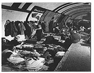
Londoners sheltering from The Blitz in a tube station
London Transport announced a scheme for the expansion and modernization of the network entitled the new work program, which had followed the announcement of improvement proposals for the Metropolitan Line. This consisted of plans to extend some lines, to take over the operation of others from main-line railway companies, and to electrify the entire network. During the 1930s and 1940s, several sections of main-line railways were converted into surface lines of the Underground system. The oldest part of today’s Underground network is the Central line between Leyton and Loughton, which opened as a railway seven years before the Underground itself.
London Transport also sought to abandon routes which made a significant financial loss. Soon after the LPTB started operating, services to Verney Junction and Brill on the Metropolitan Railway were stopped. The renamed Metropolitan Line terminus was moved to Aylesbury.
The outbreak of World War II delayed all the expansion schemes. From mid-1940, the Blitz led to the use of many Underground stations as shelters during air raids and overnight. The Underground helped over 200,000 children escape to the countryside and sheltered another 177,500 people. The authorities initially tried to discourage and prevent people from sleeping in the tube, but later supplied 22,000 bunks, latrines, and catering facilities. After a time there were even special stations with libraries and classrooms for night classes. Later in the war, eight London deep-level shelters were constructed under stations, ostensibly to be used as shelters (each deep-level shelter could hold 8,000 people) though plans were in place to convert them for a new express line parallel to the Northern line after the war. Some stations (now mostly disused) were converted into government offices: for example, Down Street was used for the headquarters of the Railway Executive Committee and was also used for meetings of the War Cabinet before the Cabinet War Rooms were completed; Brompton Road was used as a control room for anti-aircraft guns and the remains of the surface building are still used by London’s University Royal Naval Unit (URNU) and University London Air Squadron (ULAS).
After the war one of the last acts of the LPTB was to give the go-ahead for the completion of the postponed Central Line extensions. The western extension to West Ruislip was completed in 1948, and the eastern extension to Epping in 1949; the single-line branch from Epping to Ongar was taken over and electrified in 1957.
REFERENCE
1) U.S. Department of Labor Elaine L. Chao, Secretary Occupational Safety and Health Administration John L. Henshaw, Assistant Secretary “Underground Construction (Tunneling)”
2) Paulo Henrique Tsingos, Civil Engineer, UFPr “Guidelines for injection in underground construction and tunneling”
3) Training Notes by Prof. Bancy Mati “Underground Tanks”
4) K. Hiromoto, H. Hashiguchi, Y. Arai Tokyo Metro Co.,Ltd, Renovation & Construction Department, Tokyo, Japan “Large-Scale Improvement of Converting a Japan’s First Subway Station Constructed by the Shield Tunneling Method into that of an Open-Cut Method”
5) H. Hendarto, J.R. Standing Imperial College London, London, UK “Ground response to tunnel construction for Jakarta Mass Rapid Transit Project”
6) David A Dixon Atomic Energy of Canada Limited “Backfilling Techniques and Materials in Underground Excavations”
7) Dr Ákos Tóth “Tunneling and Underground Construction Technology”
8) International Telecommunication Union Telecommunication Standardization Sector Of Itu “Methods for inspecting and repairing underground plastic ducts”
We at engineeringcivil.com are thankful to Sir Laxmanagouda for submitting this paper to us.
If you have a query, you can ask a question here.