India has been plagued by some catastrophic earthquake tremors in past that have caused loss of property and human beings:
| Date | Location | Effect | Magnitude |
| January 3, 2016 | North East India | 11 dead, 200 injured | 6.7 |
| May 12, 2015 | Northern India, North East India, Bihar West Bengal (Epicenter at Nepal) | 218 (44 killed in India) | 7.3 |
| April 25, 2015 | Northern India, North East India, Gujarat (Epicenter at Nepal) | 8,900+ | 7.8 |
| September 18, 2011 | North East India, Gangtok, tremors felt in Delhi, Kolkata, Lucknow and Jaipur | 118 | 6.9 |
| October 8, 2005 | Kashmir | 1,30,000 | 7.6 |
| December 26, 2004 | Third deadliest earthquake in the history of the world, the tsunami generated off west coast northern Sumatra, India, Sri Lanka, Maldives | 283106 (15000 killed in India) | 9.1 |
| January 26, 2001 | Gujarat | 20,000 | 7.6/7.7 |
However, during the earthquake in New Zealand on 3rd September 2010 (magnitude on Richter’s scale: 7.0), only 2 people were injuredwhich was caused by falling masonry and glass. Interestingly, the said earthquake had struck when most people were asleep. Therefore it is clear that “EARTHQUAKES DON’T KILL PEOPLE, BUILDINGS DO!”
According to BIS 1893-1966 (Criteria for Earthquake Resistant Design of Structures), India was divided into 7 seismic zones, zone-0 to zone-VI. Later,In BIS 1893-1970, it was revised to zone-I to zone-V. Now, as per the latest version of BIS 1893-2002, zone-I has been merged with zone-II, and only seismic zones II to V exist (refer Figure 1) in India, where zone-II is the least earthquake prone zone, and zone-V is the highest.
Table 1: Zoning of India and corresponding Richter’s magnitude
| Seismic Zone | Mercalli Intensity Scale (MSK64) | Richter’s magnitude |
| II | VI (or less) | Upto 4.9 |
| III | VII | 5.0-5.9 |
| IV | VIII | 6.0-6.9 |
| V | IX (and above) | 7.0 and above |

Figure1 : Seismic zoning of India as per BIS1893-2002
HOW TO MAKE OUR BUILDING/STRUCTURE SAFE AGAINST EARTHQUAKE?
1. Proper seismic loading analysis (static and dynamic) as per BIS1893, load combinations and subsequent design engineering of various structural elements (footing, column, beam, slab, tie beam etc). [software namely ETABS, SAFE, STAAD Pro are the prevalent tools for analysis and engineering design]
2. Proper detailing of structural elements as per BIS13920:1993, reaffirmed 2003 (Ductile detailing of RC Structures Subject to Seismic Forces), which is applicable for seismic zones III, IV and V.
3. Retrofitting of existing structures supported on load bearing masonry walls.
SALIENT POINTS OF BIS1893 AND BIS13920 THAT SHOULD BE CONSIDERED DURING DESIGN ENGINEERING/DETAILING/CONSTRUCTION OF NEW RCC BUILDINGS/STRUCTURES LOCATED IN SEISMIC ZONES III, IV & V:
• During design using BIS1893, the structure should be designed as OMRF (Ordinary Moment Resisting Frame), if it is designed and detailed as per BIS456:2000, but not meeting ductile detailing requirement of BIS13920. However, if specially detailed to provide ductile behavior and comply to requirements of BIS13920, the structure should be designed as SMRF (Special Moment Resisting Frame), where R (response reduction factor, defined in BIS1893) is higher than that for OMRF, thus considering considerably less seismic base shear and making the structure more ductile and resistant to earthquake.
• On analysis, storey drift should never exceed (Storey height/250), as per BIS1893.
• Minimum grade of concrete to be used should be M20.
• High yield strength deformed steel bars, produced by the thermo-mechanical treatment process of grades Fe 500 and Fe 550 having elongation more than 14.5% and conforming to other requirements of BIS1786:2008 may be used for the reinforcement.
• Any reinforcement bar having higher elongation percent and UTS: YS ratio possesses better ductility. Thus satisfying Table 3 of BIS1786:2008, Fe500D and Fe550D use is advisable, where minimum elongation percent requirement is greater than 14.5%. Tata Tiscon has Fe500D rebar grade in market. The properties requirement of Fe500D as per BIS1786, and the properties available in Tata Tiscon Fe500D are given as follows:
| Mechanical/Chemical Properties | Unit | BIS 1786 Fe500D requirement | TATA TISCON Fe500D properties |
| Carbon | % | 0.250 max | 0.250 max |
| Carbon Equivalent (C + Mn /6) | % | 0.420 max | 0.400 max |
| Sulphur | % | 0.040 max | 0.035 max |
| Phosphorous | % | 0.040 max | 0.035 max |
| S + P | % | 0.075 max | 0.070 max |
| Yield strength (YS) | MPa | 500 min | 500 min |
| Ultimate Tensile strength (UTS) | MPa | 565 min | 580 min |
| UTS/YS | Ratio | 1.10 min | 1.12 min |
| Total Elongation | % | 16 min | 18 min |
• Apart from Fe500D grade, Tata Tiscon has “SD” (Super Ductile) grade of rebar, where “SD” is confirming to Fe500D requirements of BIS1786-2008, only having higher UTS/YS ratio, and hence better for highly seismic prone areas in India. However, “SD” grade of rebar is available at selected locations in India, which are highly seismic prone and generally falls in seismic zones IV and V. The features and properties requirement of “SD” versus “500D” grade is shown below. [refer Figures2 & 3]
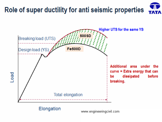
Figure2 : Fe500D vs SD (Higher UTS for same YS)
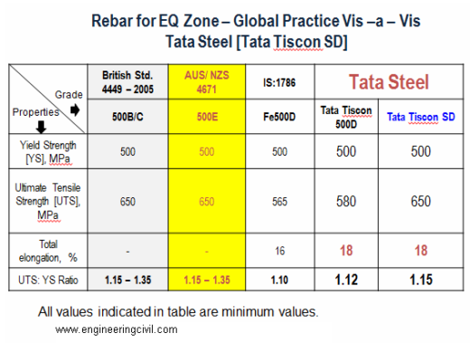
Figure3 : Fe500D vs SD properties
• Anchorage of beam longitudinal bars beyond column face in an external beam-column joint = Ld + 10d, where Ld = development length in tension as per Cl. 26.2.1 of BIS456:2000, d = nominal dia of rebar. [refer Figure4]
• At location of rebar splice (lap), centre-to-centre spacing of stirrups should not exceed 150 mm. [refer Figure5]
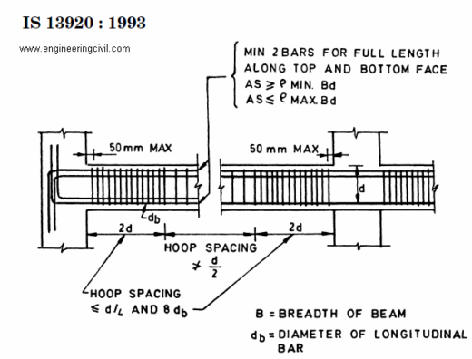
• Minimum and maximum percentage of longitudinal reinforcement in beam should satisfy requirements of BIS13920. As shown in Figure 6, the spacing of stirrups should be satisfied. However, nowhere spacing of hoops should be less than 100 mm. Minimum dia of hoop bar should be 6 mm. In beams with clear span exceeding 5m, the minimum bar dia should be 8mm.

Figure 4

Figure 5
• Stirrups with 135
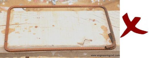
Figure7: Wrong practice as per BIS13920
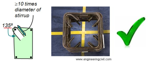
Figure7a: Correct practice as per BIS13920
• Special confining reinforcement should be provided in form of stirrups in all beam-column joints and column-footing joints, as per the provisions and clauses given in BIS13920. [refer Figure8]
• The spacing of hoops used as special confining reinforcement shall not exceed 1/4 of minimum member dimension but need not be less than 75 mm nor more than 100 mm.
• Shear walls are integral part of lateral load resisting system of the structure, and to show ductile behaviour, should be designed and detailed as per provisions and clauses given in BIS1893 and BIS13920.
• Percentage of permissible increase in Allowable Bearing Pressure, Resistance in soils, and minimum N-values (SPT value, i.e, standard penetration test value of soil) should satisfy table 1 of BIS1893.
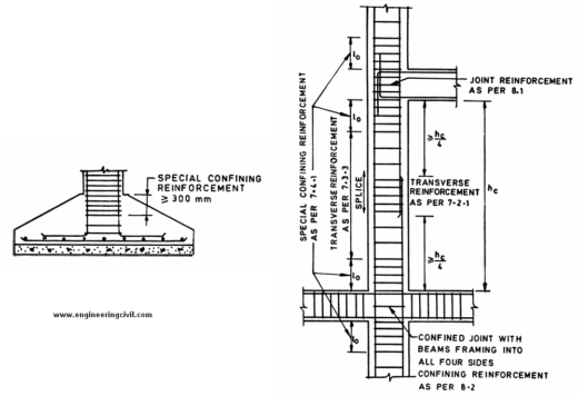
Fig 8: Special confining reinforcement provisions as per BIS13920
Disclaimer: This document aims only at highlighting good construction practises and meaningful applications to make RCC structures with proper safety/stability considerations. In any case the desired result is not obtained on following the write-up, the author shall not be responsible.
We at engineeringcivil.com are thankful to Sir Sourav Dutta for submitting this very useful information to us. We hope this will be of great use to all the civil engineers who are looking for information on Stability of RCC structure during earthquake
If you have a query, you can ask a question here.


