by Carl R. Schultheisz, Alan S. Kushner (National Transportation Safety Board), Toshio Nakamura (State University of New York, Stony Brook), Justin Ocel (Federal Highway Administration), William Wright (Virginia Polytechnic Institute and State University) and Min Li (SIMULIA Central)
Abstract
The National Transportation Safety Board (NTSB) investigates accidents to identify the probable cause and to make recommendations that would prevent similar accidents. Following the collapse of the I-35W bridge in Minneapolis on August 1, 2007, the NTSB worked with the Federal Highway Administration, the Minnesota Department of Transportation and other parties with information and expertise, including SIMULIA Central, to determine the circumstances that contributed to the collapse of the bridge, completing the investigation in 15 months. The NTSB concluded that the collapse of the bridge was caused by the inadequate load capacity of gusset plates used to connect the truss members, as a result of an error by the bridge design firm, Sver-drup & Parcel and Associates, Inc. The loading conditions included a combination of (1) substantial increases in the weight of the bridge caused by previous bridge modifications, and (2) the traffic and concentrated construction loads on the bridge on the day of the collapse. Evidence from the collapsed bridge structure, engineering evaluations of the design, and results from the finite element analyses used to support the investigation are reviewed.
Keywords: Bridge Collapse, Gusset Plate, Plasticity, Instability, Riks, Fasteners.
Introduction
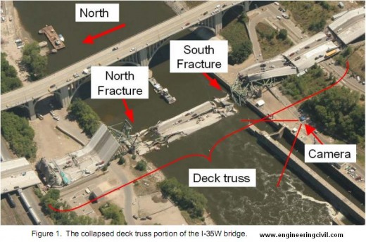
About 6:05 p.m. central daylight time on Wednesday, August 1, 2007, the eight-lane, 1,907-foot-long I-35W highway bridge over the Mississippi River in Minneapolis, Minnesota, experienced a catastrophic failure in the central deck truss span over the river. The 1,064-foot-long deck truss portion of the bridgecollapsed, along with adjacent sections of the approach spans that were supported by the deck truss. See Figure 1. A total of 190 people were confirmed to have been on or near the bridge when the collapse occurred; 13 people died, and 145 people were injured. There were 111 vehicles on the portion of the bridge that collapsed, with 17 recovered from the water.
The National Transportation Safety Board (NTSB) launched a team of investigators to the accident scene, with on-scene work beginning on the day after the collapse. The on-scene investigation, including documentation and analysis of the recovered bridge structure, lasted until November 10, 2007. The results of the investigation were presented in the NTSB’s final report [NTSB 2008k], which was adopted on November 14, 2008.
The NTSB is an independent federal agency charged with investigating all aviation accidents in the United States and investigating major accidents involving highways, railroads, pipelines, hazardous materials and marine transportation. The goals of every investigation are to determine the probable cause of the accident and to make recommendations for systemic changes that would prevent similar accidents.
In order to accomplish its mission, the NTSB collaborates with parties involved in the accident who have specialized technical knowledge or expertise that can contribute to the investigation. For the collapse of the I-35W bridge, the parties to the investigation included the Federal Highway Administration (FHWA); the Minnesota Department of Transportation (Mn/DOT) and their consultant Wiss, Janney, Elstner Associates, Inc. (WJE); Jacobs Engineering Group, Inc. (Jacobs), which purchased Sverdrup Corporation (successor to the original bridge design firm) in 1999; and Progressive Contractors, Inc. (PCI), which was repaving part of the deck on the day of the accident.
Bridge design
The I-35W bridge was designed by the engineering consulting firm of Sverdrup & Parcel and Associates, Inc., of St. Louis, Missouri. The design was based on the 1961 American Association of State Highway Officials (AASHO) Standard Specifications for Highway Bridges and 1961 and 1962 Interim Specifications, and on the 1964 Minnesota Highway Department Standard Specifications for Highway Construction. The bridge design was developed over several years. Plans for the foundation were approved in 1964 and construction of some piers began in 1964. The final design plans for the bridge were certified by the Sverdrup & Parcel project manager (a registered professional engineer) on March 4, 1965. The bridge design plans were approved by the Minnesota Highway Department on June 18, 1965.
Bridge construction
The bridge was 1,907 feet long and carried eight lanes of traffic, four northbound and four southbound. The bridge had 13 reinforced concrete piers and 14 spans, numbered south to north. Eleven of the 14 spans were approach spans to the deck truss portion. The bridge deck in the approach spans either was supported by continuous welded steel plate girders or by continuous voided slab concrete spans. The south approach spans were supported by the south abutment; by piers 1, 2, 3, and 4; and by the south end of the deck truss portion. The north approach spans were supported by the north abutment; by piers 9, 10, 11, 12, and 13; and by the north end of the deck truss portion. The 1,064-foot-long deck truss portion of the bridge encompassed a portion of span 5; all of spans 6, 7, and 8; and a portion of span 9. The deck truss was supported by four piers (piers 5, 6, 7, and 8).
The original bridge design accounted for thermal expansion using a combination of fixed and expansion bearings for the bridge/pier interfaces. The fixed bearing assemblies were located at piers 1, 3, 7, 9, 12, and 13. Expansion (sliding) bearings were used at the south and north abutments and at piers 2, 4, 10, and 11. Expansion roller bearings were used at piers 5, 6, and 8.
The deck of the I-35W bridge consisted of two reinforced concrete deck slabs separated by about 6 inches. The total width of the deck slabs was about 113 feet 4 inches. When the bridge was opened to traffic in 1967, the cast-in-place concrete deck slab had a minimum thickness of 6.5 inches. As discussed later in this report, bridge renovation projects eventually increased the average thickness of the concrete deck by about 2 inches.
Deck truss portion of the bridge
In a deck truss bridge, the roadbed is along the top of the truss structure. The deck truss portion of the bridge consisted of two parallel main Warren-type trusses (east and west) with verticals. A Warren truss has alternating tension and compression diagonals and has the advantage that chord members are continuous across two panels, with the same force carried across both panels. This arrangement simplifies some of the design calculations.
The upper and lower chords of the main trusses extended the length of the deck truss portion of the bridge and were connected by straight vertical and (except at each end of the deck truss) diagonal members that made up the truss structure. The upper and lower chords were welded box members, as were those diagonals and verticals that were designed primarily for compression. The vertical and diagonal members designed primarily for tension were H members consisting of flanges welded to a web plate.
Gusset plates were used to connect the truss members. The gusset plates were primarily attached to the truss members with rivets, but a few bolts were used at each joint, presumably to expedite the initial connection during construction.
The east and west main trusses were spaced 72 feet 4 inches apart. The deck was supported by 27 transverse welded floor trusses spaced on 38-foot centers along the main trusses and by two floor beams at the north and south ends. The floor trusses were cantilevered out about 16 feet on either side past the east and west main trusses. The concrete deck for the roadway rested on 27-inch-deep wide-flange longitudinal stringers attached to the transverse floor trusses and spaced on 8-foot-1-inch centers. The 14 stringers were continuous for the length of the deck truss except for five expansion joints. Diaphragms connected the webs of adjacent stringers to transfer lateral loads and maintain structural rigidity and geometry.
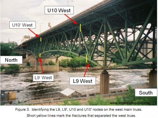
The main truss nodes were numbered from the south beginning from 0, reaching node 14 at the center of the deck truss above the river. Because the bridge was nearly symmetric north to south, the nodes on the north end of the bridge were numbered in reverse order and given a prime symbol, so that U10 and U10? indicate symmetric nodes with respect to the center of the deck truss. The letters U (for upper chord) and L (for lower chord) further identified the nodes, along with E or W to specify the east or west main truss.
These node numbers were also used to identify the connecting main truss structural members. For example, the upper chord member that connected the U9 node to the U10 node was designated U9/U10 (or U10/U9). Again, E and W were used to designate the east or west main truss.
For the most part, forces were only transferred between truss members at the nodes where the diagonals connected to the upper and lower chords. These nodes alternated between the upper and lower chords along the bridge, so that, for example, L9, U10 and L11 are nodes where forces are transmitted. Conversely, the chord members were continuous through nodes U9, L10 and U11, with only a token connection to the verticals for stability, and no forces were intended to be transferred to other members at those nodes. Loads from the transverse floor trusses tied into the verticals at a point between the upper and lower chords. As a result, at U10, the vertical was in tension, while at L9 or L11, the vertical was in compression.
The deck truss portion of the bridge was also stiffened by sway braces at each panel point below the floor trusses, and by angled lateral braces extending between panel points.
Bridge history
The bridge was opened to traffic in 1967. The original dead weight of the deck truss portion of the bridge was estimated to be 18.3 million pounds. Two later modifications to the bridge caused significant increases in the weight of the deck truss portion of the bridge. In 1977, a renovation project involved milling the bridge deck surface to a depth of 1/4 inch and adding a wearing course of 2 inches of low-slump concrete, adding some 3 million pounds to the deck truss portion of the bridge. This project was intended to provide additional protection against corrosion for the steel reinforcing bars in the deck. In 1998, the median barrier and outside railings were upgraded to meet revised standards, adding 1.2 million pounds to the deck truss portion of the bridge.
During the summer of 2007 until the day of the collapse, renovation work was underway to remove the concrete wearing course to a depth of 2 inches and add a new 2-inch-thick concrete overlay. At the time of the bridge collapse, four of the eight travel lanes (the two outside lanes northbound and the two inside lanes southbound) were closed to traffic. The preexisting wearing surface was still in place on the two inside lanes northbound, where the average deck thickness was 8.7 inches. The new overlay was already in place on the two outside northbound lanes (average deck thickness of 8.8 inches) and the two outside southbound lanes (average deck thickness of 8.9 inches). The surface of the two inside southbound lanes had been milled for the entire length of the bridge, removing about 2 inches of material.
On the day of the collapse, aggregates and equipment for the repaving project were staged on the center span of the deck truss portion of the bridge. The construction aggregates were distributed in eight adjacent piles (four truckloads of sand and four of gravel) placed along the median in the leftmost southbound lane just north of pier 6. Along with the aggregates in this area were a water tanker truck with 3,000 gallons of water, a cement tanker, a concrete mixer, one small loader/excavator, and four self-propelled walk-behind or ride-along buggies for moving smaller amounts of materials. The documented delivered weights for the aggregates staged on the bridge were 184,380 pounds of gravel and 198,820 pounds of sand. The estimated weight of the parked construction vehicles, equipment, and personnel in this area was 196,000 pounds. Figure 2 is a photograph showing the sand and gravel piles about 2 hours before the collapse.

Figure-2 The locations and weights of the construction materials and vehicles
A post-accident survey was made to identify all of the vehicles, workers and construction materials on the bridge at the time of the collapse [NTSB 2007]. The locations of the vehicles, workers and materials were determined from witness statements and photogrammetry. Each vehicle was weighed if possible, or the weight estimated from a vehicle database. Weather data was also collected for the area on the day of the collapse.
Findings from the wreckage and the video
The disposition of the wreckage indicated that the collapse initiated in the central span of the deck truss portion of the bridge, with the structure north and south of the river being pulled toward the river. The bridge components were examined and the damage documented [NTSB 2008b], and the locations of the bridge components and the observed damage were used to identify the sequence of the collapse [NTSB 2008g].
The deck truss portion of the bridge separated into three sections. The separations occurred at symmetric positions north and south of the center of the bridge, through both the east and west trusses. Fractures through the U10 and U10? gusset plates severed the connections of the upper chords and the connections between the L9/U10 and L9?/U10? compression diagonals and the central section of the bridge. The lower chords were severed by fractures through the L9/L10 and L9?/L10? members adjacent to the gusset plates at the L9 and L9? nodes. The positions of the fractures are indicated in Figure 1 and in a pre-collapse photograph in Figure 3.
Evidence from a motion-activated video surveillance camera on the south side of the river indicated that the south end of the bridge began to fall before the north end, so the investigation concentrated on the fractures in the U10 gusset plates and the L9/L10 lower chord members [NTSB 2008e]. The video also showed that the bridge fell without appreciable side-to-side rotation, indicating that the fractures on the east and west trusses occurred nearly simultaneously.
Residual plastic deformation showed that the fractures in the L9/U10 lower chord members adjacent to the L9 nodes occurred under severe bending, which would only have been possible if the truss was already fractured at another location and the opposite ends of the members were free to move. These fractures were therefore not primary, and the focus of the investigation shifted to the U10 gusset plates.
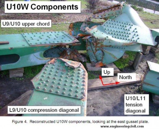
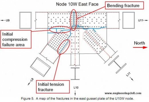
The deformation and fractures in the U10 gusset plates surrounding the upper ends of the L9/U10 compression diagonals were consistent with the in-plane loads expected in the truss. See Figures 4 and 5. The damage was consistent with bending and tearing of the gusset plates under compression above the ends of the L9/U10 diagonals, with fractures under tension through the bottom rows of rivets on the L9/U10 diagonals adjacent to the verticals. These fractures in the U10 gusset plates left a portion of each gusset plate attached to the upper ends of the separated diagonals L9/U10, with a V-shaped piece of each gusset plate extending beyond the ends of the diagonals. On both the east and west diagonals, these V-shaped pieces were bent toward the east, indicating that the upper ends of the diagonals shifted laterally to the west as the gusset plates deformed and fractured, and the east side plates of the diagonals penetrated through the interior structure of the nodes.
The loss of structural support from the bending and fracturing of the U10 gusset plates and the lateral shift of the L9/U10 diagonals allowed the remainder of the U10 nodes to drop downward. This downward displacement resulted in bending loads that fractured the gusset plates between the upper chord members. The direction of bending showed that the U10 nodes had dropped below the levels of the U9 and U11 nodes.
The fractures on the north side of the bridge (in the U10? gusset plates and in the L9?/U10? lower chord members) were very similar to the fractures on the south side of the bridge.
Because the fractures and deformations in the U10 gusset plates were consistent with the expected loading in the truss, these gusset plates were likely points of initiation of the collapse, and therefore a primary focus of the investigation. A detailed study of the U10 gusset plates was the initial task undertaken using finite element analysis.
There was no evidence that the U10 gusset plates had any pre-existing cracking (such as from fatigue) or corrosion damage before the bridge collapse, indicating that the gusset plates failed as a result of overloading. It was therefore necessary to compare the loads on the bridge to the capacity of the design.
Review of the design
The bridge was designed using an Allowable Stress methodology, whereby the stresses arising from specified design loads were required to be less than material-specific allowable stresses. This methodology built in safety both in the specification of the design load and in the allowable stress level. The design loads included the dead load of the weight of the bridge plus a worst-case live load approximating multiple lanes of heavy trucks, and an added 50 percent of the live load to account for dynamic effects (referred to as impact). Under the applied design loads, the stress in each component was required to be less than the allowable stress for that component. This allowable stress would have been no more than 55 percent of the yield stress, depending on the type of load applied (tension, compression, or shear). The allowable stresses for truss members in compression were further decreased to guard against buckling.
Following the bridge collapse, the Safety Board received sets of design documents from both Mn/DOT and Jacobs. In addition to the design drawings, both entities provided identical collections of several hundred pages of sequentially numbered and indexed compilations of checked computation sheets showing calculations performed for the final design of the bridge. The computation sheets for the deck truss superstructure contained design calculations for the welded gusset plates used in the floor trusses, but none of the records from Mn/DOT or Jacobs Engineering showed any calculations for the gusset plates on the main trusses.
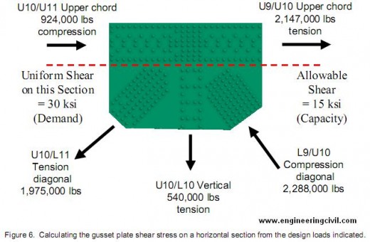
Using a basic design methodology consistent with that used by Sverdrup & Parcel to design the gusset plates for the floor trusses, FHWA engineers calculated the stresses on the main truss gusset plates that would be generated by the design loads (demand) in the members secured by the gusset plates [Holt 2008]. Comparing these stresses to the allowable stresses (capacity) in the AASHO specifications resulted in demand-to-capacity (D/C) ratios that illustrate the expected performance of the gusset plates. A D/C ratio of slightly greater than 1 (demand exceeds design capacity) are sometimes acceptable based on the professional judgment of an engineer. A D/C ratio significantly greater than 1 likely indicates a design error.
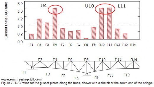
The evaluations considered stresses on two critical sections in each gusset plate – one horizontal section near the center of the gusset along the edge of the chord members, as shown in Figure 6, and one vertical section adjacent to the vertical member of the node. Results of the horizontal section calculations are provided in Figure 7, showing that the gusset plates at the U4, U10, and L11 nodes had D/C ratios for shear that exceeded 2. In addition, the gusset plates at two other nodes had D/C ratios slightly over 1 for shear. The analysis indicates that the gusset plates at the U4, U10, and L11 nodes were only half as thick as necessary to meet the design requirements.
Lines of corrosion were found on the L11 gusset plates along the upper edges of the lower chord members. The L11 gusset plates were fractured at or near the lines of corrosion, separating the vertical and diagonals from the lower chord members. The gusset plates were intact along the lower chord members, maintaining continuity along the lower chord through the node. Because the stress evaluation showed that the L11 gusset plates were only about half as thick as required, there was concern that the inadequate gusset plate thickness coupled with the corrosion might have played a role in the collapse. A detailed study of the gusset plates at the L11 nodes with corrosion was therefore an additional task undertaken using finite element analysis.
Finite element analysis
The NTSB formed a group to perform finite element analyses in support of the investigation. In addition to participation in the group by parties to the investigation, the NTSB acquired added expertise and resources through an external contract with the State University of New York at Stony Brook and a subcontract with the Central Office of Dassault Systemes SIMULIA Corporation (SIMULIA Central). All of the analyses were performed using Abaqus/Standard. A parallel investigation was undertaken by the Federal Highway Administration Turner-Fairbank Highway Research Center (TFHRC) in collaboration with this effort, and the investigation relied heavily on global models of the bridge that were constructed at the FHWA TFHRC. Details of the analyses are provided in several reports [Ocel 2008, NTSB 2008c, NTSB 2008j].
Information gained from examining the wreckage was used to guide the modeling effort and evaluate results. Based on findings from the accident scene, the modeling was initially focused on the U10 nodes. The modeling effort was expanded to include the L11 nodes as a result of the FHWA’s gusset plate adequacy analysis, which showed that the gusset plates at both the U10 and L11 nodes had inadequate load capacity, coupled with the fact that the L11 gusset plates were found to have areas of corrosion, which further reduced their load-carrying capacity.
Inputs to the modeling effort
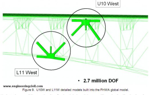
The models were based on the original Sverdrup & Parcel design plans and the Allied Structural Steel shop drawings. The FHWA developed a three-dimensional global model of the entire deck truss portion of the bridge, constructed with beam and shell elements. See Figure 8. In addition, both the FHWA and SUNY/SIMULIA created detailed models of the U10 and L11 nodes to examine the fine details of stress distribution. These detailed models were built into the FHWA global model of the bridge. See Figure 9. The FHWA detailed model generally used shell-element representations for the truss members and the gusset plates, while the SUNY/SIMULIA detailed models used solid-element representations; the solid-element approach was in part motivated by a goal of considering stress concentrations associated with the riveted connections.

The boundary conditions at the piers for the global model were calibrated using live load strain gauge data obtained by the University of Minnesota as part of a 1999 fatigue assessment of the I-35W bridge. The data fell between results from a model with fixed bearings and a model with free bearings. Good agreement was obtained with a model using fixed bearings, but including flexibility in the concrete piers. The approach spans supported at each end of the deck truss portion of the bridge were replaced with spring elements.
Loads were applied in steps to mimic the history of the bridge. The original weight of the as-built bridge was calculated by the FHWA from a careful audit of the steel called out in the shop drawings. The thickness of the deck in different areas of the bridge was based on cores taken after the accident. In the initial load step, the weight of the concrete was applied using forces only to model wet concrete. In the next load step, the concrete forces were replaced with shell elements to model the hardened concrete. Subsequent load steps included the increase in weight associated with the 1977 increase in deck thickness, the increase in weight associated with the 1998 change in the median barrier and outside railings, and the decrease in weight associated with the removal of part of the deck in the repaving operation that was underway at the time of the collapse. The final load steps introduced the traffic and the construction loads on the bridge at the time of the accident [NTSB 2007].
Photographs from 1999 and 2003 were used by NTSB to estimate the magnitude and direction of bowing distortion in the U10W and U10E gusset plates for input to the models [NTSB 2008f]. See Figure 10. The bowing distortion was included as an initial imperfection. The estimate of the maximum bowing magnitude used for input to the models was 0.60 ± 0.15 inch. To generate bowing consistent with that shown in the photographs, it was necessary to use an initial maximum deflection of 0.5 inch in the unloaded model, which increased to 0.6–0.7 inch after application of the original bridge dead load plus the added deck and the modified barriers (the loading condition at the time the bowed gusset plates were photographed).

Measurements of the loss of thickness in the L11 gusset plates were made using a point micrometer and with a laser scanner attached to a coordinate-measuring-machine arm [NTSB 2008h]. The measurements from the four different gusset plates (two each at L11E and L11W) were averaged and incorporated in the models as a strip of reduced thickness in the gusset plates along the upper edges of the chord members being connected.
Gusset plate material properties were based on tensile tests performed by the FHWA on samples from undamaged areas of the four U10E and U10W gusset plates [Beshah 2008]. The measured yield stresses of all of the tensile test samples exceeded the final design plan specified minimum tensile yield stress of 50 ksi. Rivet properties were estimated from hardness measurements performed by the NTSB [NTSB 2008a, NTSB 2008d].
Selected results from the modeling effort
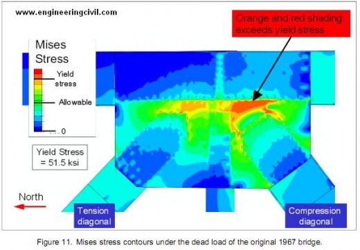
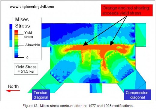
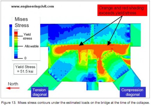
The models showed that the U10 gusset plates were loaded beyond their yield stress under the dead weight of the as-built 1967 bridge (Figure 11). At that stage of loading, the areas of yielding were confined to a small area above the ends of the L9/U10 compression diagonals. As the weight of the bridge was increased by the 1977 and 1998 modifications, the areas above the yield stress expanded around the ends of the L9/U10 compression diagonals, and the areas above the ends of the U10/L11 tension diagonals began to yield as well (Figure 12). Under the added weight of the traffic and construction materials and vehicles on the day of the accident, almost all of the U10 gusset plates surrounding the upper end of the L9/U10 compression diagonal were yielding (Figure 13). Because the construction materials were staged on the west side of the bridge, the U10W gusset plates were yielding to a greater extent than those at U10E, with instability therefore occurring first at U10W.
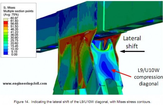
The yielding of the U10W gusset plates surrounding the upper end of the L9/U10W compression diagonal created a plastic hinge in the structure, and the finite element analysis indicated that the collapse initiated by a local bending instability in the U10W gusset plates. This instability allowed for a lateral shift of the upper end of the L9/U10W diagonal, as indicated in Figure 14, removing support from the central portion of the bridge.
The bending instability in the gusset plates first manifested itself as a failure to converge under increasing load. The instability was further studied and confirmed as a structural instability using Riks analysis and using an applied displacement approach. In the applied displacement approach, the displacement increment associated with a small load increment just before the onset of instability was calculated, and that displacement increment was extrapolated and used as a boundary condition. In the Riks analysis and the applied displacement approach, the bending of the gusset plates and lateral shift of the upper end of the L9/U10 diagonal was shown to increase under decreasing load.
The majority of the analyses used simplified Abaqus fasteners to model the riveted connections. Stress concentrations associated with rivets were investigated using submodels with detailed three dimensional models of the rivets in the most highly stressed areas. These models indicated that no material failure would be expected in the gusset plates before the onset of instability.
Beyond the point of instability, the Riks analysis and the applied displacement approach showed that the deformation in the gusset plates would reach levels where material failure would be expected. Peak stresses and strains appeared in locations consistent with the fractures observed in the post-accident examination of the wreckage.
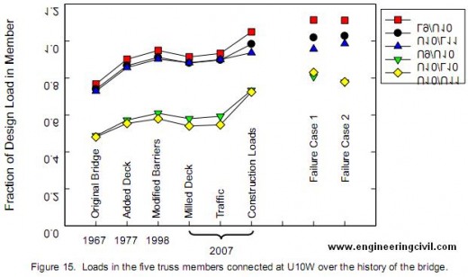
The design loads for the five truss members that joined at U10W are shown in Table 1. The loads in those members over the history of the bridge are shown in Figure 15. The figure shows that the members were at the most about 5 percent above their design loads under the best estimate of the conditions on the bridge at the time of the collapse. The intent of the design methodology should have ensured that, under the design load, the stress in the gusset plates would have been no more than 55 percent of the yield stress. The yielding in the gusset plates under only the dead weight of the original 1967 bridge confirms the inadequate thickness of the gusset plates identified in the FHWA design review.
| U9/U10 | L9/U10 | U10/L10 | U10/L11 | U10/U11 | |
| Design load (kips) | 2,147 | 2,288 | 540 | 1,975 | 924 |
| Mode | Tension | Compression | Tension | Tension | Compression |
Figure 15 also shows that the concentration of the construction materials and vehicles above U10W increased the loads in the members significantly, but the most highly loaded member (L9/U10) was estimated to be only about 5 percent above its design load. Properly designed gusset plates should still have has a significant margin of safety under these loading conditions. Also, the increase in load arising from the construction materials and vehicles was similar to that associated with the 1977 increase in deck thickness. Thus, it was concluded that the concentrated stockpiling of construction materials and vehicles on the bridge could not be identified as the sole cause of the collapse. The increases in load over the history of the bridge were part of the circumstances that triggered the collapse, but they would not have been sufficient to cause the collapse if the main truss gusset plates had met their design requirements.
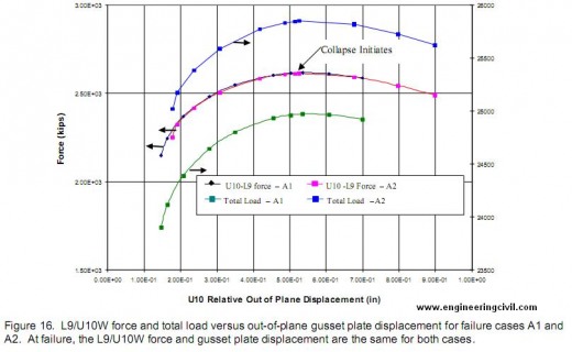
In order to trigger the instability, it was necessary to increase the loads above the best estimate of the loads on the bridge at the time of the collapse, as indicated by the two failure cases shown in Figure 15. In one case, only the construction loads were increased, while in the second case, all of the loads were increased. Figure 15 shows that the load in the L9/U10W necessary to trigger failure was the same in both cases, about 5 percent higher than the L9/U10W load under the best estimate of the collapse loads. Comparing the two failure cases showed that the instability was triggered at a critical value of the load in the L9/U10W diagonal and a critical magnitude of the out-of-plane bending displacement of the gusset plates. Figure 16 shows this result clearly for the two failure cases (labeled A1 and A2 in the figure). Figure 16 plots both the load in the L9/U10W diagonal and the total load on the bridge as functions of the lateral displacement on a point on the outside U10W gusset plate. The load in the L9/U10W diagonal and the displacement follow nearly identical paths for the two failure cases considered, even though the total loads on the bridge are significantly different.
Including the photographically documented bowing distortion of the U10W gusset plates in the model reduced the load required to trigger instability and changed the direction of the deformation. With the U10W gusset plates bowed in the directions shown in the photographs, the upper end of the L9/U10W diagonal shifts to the outside of the bridge at instability, consistent with the direction that the diagonal was observed to have shifted by the examination of the collapsed bridge structure. With initially flat U10W gusset plates in the model, the upper end of the L9/U10W diagonal shifted toward the inside of the bridge at instability, which is not consistent with the collapsed bridge structure. The source of the bowing distortion was not identified, but a relatively large initial imperfection was required to match the deformation under the loading conditions at the time when the photographs were taken. Incorporating the stress that caused the bowing would likely reduce the load necessary to trigger instability. The choice of the shape of the initial imperfection for the bowing distortion had an effect on the results.
Both the FHWA and SUNY/SIMULIA models were also used to evaluate the effect of corrosion in the L11 node gusset plates. The corroded condition of these gusset plates was modeled as a local thickness reduction of 0.1 inch (section loss of 20 percent) running along the top of the lower chord members. Stresses in both the U10 and L11 gusset plates exceeded the yield stress under only the dead load of the original 1967 bridge design. The models showed that the maximum stress in the gusset plates of the L11 nodes occurred in the area of corrosion at the lower end of tension diagonal U10/L11W, but that the stresses in the U10W gusset plates were substantially higher than the stresses in the corroded L11W gusset plates under the conditions at the time of the collapse. The models also predicted that the corroded L11 nodes would support much higher loads than those necessary to trigger the instability at U10W. The effects of changes in temperature at the U10 nodes were also studied with the models. Data from a weather station at the University of Minnesota showed that, on the day of the collapse, the temperature increased from a low of 73.5° F earlier in the day to 92.1° F at 6:01 p.m [NTSB 2007]. In the FHWA global model, the bearings were assumed to be fixed (but with flexibility in the piers), so that a temperature change would affect the stresses. The models showed that an increase in temperature reduced the stress in the U10 gusset plates, and thus a slightly higher applied load was required to trigger the bending instability and the lateral shift of the upper end of diagonal L9/U10W.
The FHWA investigated an additional case allowing for a difference in temperature on the east and west trusses as a result of solar radiation [NTSB 2008i]. When compared to a case with a uniform temperature change, the effects of the temperature differentials between the two trusses were minimal, with the member forces at the U10W and U10E nodes changing by less than 2 percent in the chords and diagonals and by less than 5 percent in the verticals.
Summary
The NTSB concluded that the probable cause of the collapse was the inadequate capacity of the U10 gusset plates, which resulted from an error by the original bridge design firm, who failed to perform all of the necessary calculations to properly design the main truss gusset plates. The U10 gusset plates failed under the combined loads arising from the original bridge weight, the increases in weight caused by modifications to the bridge, along with traffic and the construction vehicles and materials staged on the bridge in an area concentrated above the U10 nodes. A review of the design showed that the U10 and L11 gusset plates were only half as thick as necessary to meet the design specifications. The finite element analysis confirmed the inadequacy of the U10 and L11 gusset plates, which were yielding under only the dead weight of the original 1967 bridge. Gusset plates that met the design specifications would have retained a significant margin of safety under the loads on the bridge on the day of the collapse.
The finite element analysis indicated that the collapse was triggered by a local bending instability in the U10W gusset plates, which occurred before any material failure or fracture. The computations also showed that the instability would have been triggered at U10W before U10E or either of the L11 nodes, even when including corrosion on the L11 gusset plates in the models. Including the bowing distortion in the U10 gusset plates that was observed in the photographs decreased the load necessary to trigger the instability, and also directed the lateral shift of the upper end of the L9/U10W diagonal to the outside of the bridge, consistent with the observations of the wreckage. Finally, the finite element analysis indicated that the temperature changes on the day of the collapse would have had a minimal effect on the load necessary to trigger the instability in the U10W gusset plates.
References
1. Beshah, F., Wright, W., and Graybeal, B., “Mechanical Property Test Report (I-35W over the Mississippi River),” Federal Highway Administration Turner-Fairbank Highway Research Center Report, October 15, 2008.
2. Holt, R., and Hartmann, J., “Adequacy of the U10 Gusset Plate Design for the Minnesota Bridge No. 9340 (I-35W over the Mississippi River), Final Report,” Federal Highway Administration Turner-Fairbank Highway Research Center Report, October 18, 2008.
3. Ocel, J.M., and Wright, W.J., “Finite element Modeling of I-35W Bridge Collapse Final Report,” Federal Highway Administration Turner-Fairbank Highway Research Center Report, October 2008.
4. NTSB 2007, Modeling Group Study 07-115, Loads on the bridge at the time of the accident, National Transportation Safety Board, Washington, D.C., November 8, 2007.
5. NTSB 2008a, Materials Laboratory Factual Report 08-006, Hardness measurements on rivets and bolts, National Transportation Safety Board, Washington, D.C., January 18, 2008.
6. NTSB 2008b, Structural Investigation Group Chairman Factual Report 08-015, National Transportation Safety Board, Washington, D.C., March 5, 2008.
7. NTSB 2008c, Modeling Group Contractor Interim Report, National Transportation Safety Board, Washington, D.C., March 7, 2008.
8. NTSB 2008d, Materials Laboratory Factual Report 08-053, Hardness measurements on U10 and L11 gusset plates, National Transportation Safety Board, Washington, D.C., May 5, 2008.
9. NTSB 2008e, Video Study, National Transportation Safety Board, Washington, D.C., June 3, 2008.
10. NTSB 2008f, Specialist’s Study Report, Gusset plate photograph measurements, National Transportation Safety Board, Washington, D.C., July 16, 2008.
11. NTSB 2008g, Materials Laboratory Sequencing Study Report 08-032, National Transportation Safety Board, Washington, D.C., October 17, 2008.
12. NTSB 2008h, Materials Laboratory Factual Report 08-096, Laser scans and corrosion measurements of L11 gusset plates, National Transportation Safety Board, Washington, D.C., October 24, 2008.
13. NTSB 2008i, Materials Laboratory Study Report 08-118, Calculation of differential temperature for I-35W bridge, National Transportation Safety Board, Washington, D.C., November 7, 2008.
14. NTSB 2008j, Modeling Group Chairman Final Report 08-119, National Transportation Safety Board, Washington, D.C., November 12, 2008.
15. NTSB 2008k, “Collapse of I-35W Highway Bridge, Minneapolis, Minnesota August 1, 2007,” Highway Accident Report NTSB/HAR-08/03 PB2008-916203, National Transportation Safety Board, Washington, D.C., November 14, 2008.
NOTE: All of the references are available from the NTSB website. The final NTSB report in reference 15 [NTSB 2008k] is at http://www.ntsb.gov/publictn/2008/HAR0803.pdf. The other reports are at http://www.ntsb.gov/Dockets/Highway/HWY07MH024.
We are thankful to Sir Matthew Ladzinski for submitting this report to engineeringcivil.com and also granting us rights to publish it on web. This report will help all civil engineers study the reason behind the Minneapolis I-35W Bridge Collapse and would also help them to designing better bridges in future.
If you have a query, you can ask a question here.


this is a good amount of info which can be used in my school project thank u so much