

Introduction:
The movement of heat across an object that is more conductive than the materials it is surrounded by is referred to as thermal bridging. Heat flows through a path of least resistance created by the conductive material. Thermal bridging can be a significant cause of energy loss in homes and buildings, resulting in increased utility bills. The object’s overall thermal resistance is reduced as a result of thermal bridges. Thermal bridges result in heat transfer into or out of conditioned space and are commonly discussed in the context of a building’s thermal envelope.
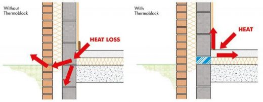
Fig 1: Concept of Thermal Bridge
Source: Civil Engineering Quora
Building thermal bridges can increase the amount of energy needed to heat and cool a space, cause condensation (moisture) within the building envelope, and cause thermal discomfort. Thermal heat bridges can cause additional heat losses and require more energy to mitigate in colder climates. The condensation can result in the growth of mould.
Thermal bridges are widespread in older structures that are ill-built, poorly insulated, and have only one skin and a single pane of glass.
Thermal bridging in a home:
The thermal envelope of a building is a layer of the building enclosure system that prevents heat movement from the conditioned interior to the unconditioned exterior. Heat will move at different rates through a building’s thermal envelope depending on the materials used throughout the envelope. Because there is less thermal resistance at thermal bridge areas, heat transmission will be stronger than where insulation exists. When the outside temperature is lower than the inside temperature in the winter, heat flows outward and over thermal bridges at a faster rate. Heat flows inward and at higher rates through thermal bridges in the summer when the outer temperature is often higher than the internal temperature.
Thermal bridges can form in a variety of locations inside a building envelope, although they are most commonly found when two or more building elements meet. Here are a few examples of typical locations:
1. Floor-to-wall or balcony-to-wall junctions.
2. Roof/ceiling-to-wall junctions.
3. Window-to-wall junctions.
4. Door-to-wall junctions.
5. Wall-t-wall junctions.
6. Wood, steel, concrete members that are incorporated in exterior walls.
7. Frame components of windows and doors.
8. Metal ties in masonry cavity walls.
9. Gap areas in poorly insulated rooms.
10. Luminaries that penetrate the insulated ceiling.
Impacts of Thermal Bridging:
Due to winter heat loss and summer heat gain, thermal bridging can increase the amount of energy required to heat or cool a conditioned room. Thermal discomfort may be experienced by occupants in interior regions near thermal bridges due to temperature differences. When the temperature difference is large between indoor and outdoor, there is a risk of condensation in the building envelope. Condensation can lead to mould growth, resulting in poor indoor air quality and insulation deterioration, lowering insulation performance, and causing the insulation to function unevenly throughout the thermal envelope. Allergens, irritants, and even poisonous chemicals are produced by the moulds. Allergic reactions such as sneezing, runny nose, red eyes, and skin rash can occur after inhaling or handling mould particles. Asthma attacks and other respiratory disorders can also be caused by moulds.
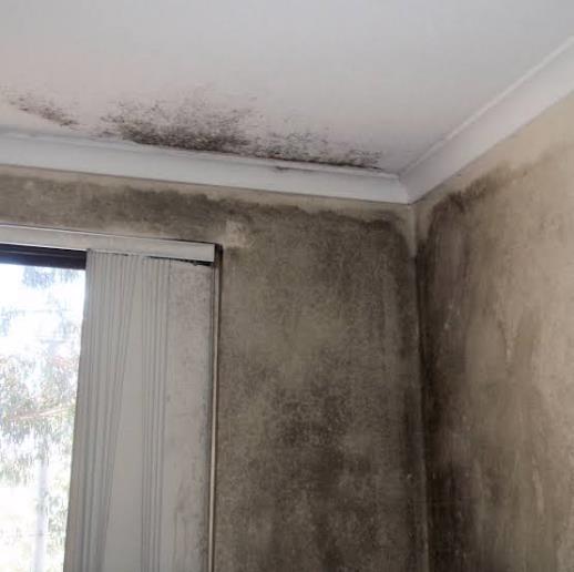
Fig 2: Impact of Thermal Bridging
Source: Buildingtalk
These severe effects are not caused by all thermal bridges. The effects of a thermal bridge on the overall energy performance of the building, occupant comfort, moisture condensation, and associated aesthetic and/or structural damage, and degradation of the building materials should all be considered when determining the severity of a thermal bridge. The design can then be corrected using the appropriate correction techniques.
How to identify Thermal Bridges?
According to ISO (International Organization for Standardization), surveying of buildings is done by passive Infrared Thermography (IRT). Thermal signals that indicate heat leakage can be detected using infrared thermography of structures. IRT detects thermal anomalies caused by fluid movement through building elements, revealing differences in the thermal characteristics of the materials that produce a significant shift in temperature.
Another method used is Laser Scanning Technology. Automated analysis approaches of this technology can provide thermal imaging of a building in 3D CAD model surfaces. Thermal irregularities of thermal bridges and insulation leaks can be identified and measured using surface temperature data in 3D models.
Thermal bridges can also be identified by using Unmanned Aerial Vehicle (UAV). In this method, multiple cameras and platforms are used. A thermal field image of recorded temperature values is generated by the UAV using an infrared camera, with each pixel representing radiative energy emitted by the building’s surface.
How to prevent Thermal Bridge?
Thermal bridging must be avoided by covering the studs with continuous insulation. Insulation can readily be added to the wall structure during home building to break the thermal bridge. A layer of insulation can only be installed from the inside or exterior of the home while rebuilding. Inside insulation is often difficult and expensive to install because it necessitates a complete rebuild to replace drywall, trim, and other interior finishes.
Design methods to control Thermal Bridges:
Depending on the reason, location, and kind of building, there are numerous solutions that have been demonstrated to eliminate thermal bridging. The goal of these strategies is to either establish a thermal break where a building component would normally span from outside to inside or to limit the amount of building components that span from outside to inside. These are some of the strategies:
1. Providing continuous thermal insulation layer in the thermal envelope.
2. Where direct continuity is not possible, the lapping of insulation is done.
3. Double and staggered wall assemblies.
4. Using Structural Insulated Panels (SIPs) and Insulating Concrete Forms (ICFs)
5. Using raised heel trusses at wall-to-roof junctions.
6. Using double or triple pane windows with gas fillers.
References:
- https://www.progressivefoam.com/thermal-bridging-and-how-to-stop-it/
- https://en.wikipedia.org/wiki/Thermal_bridge
- https://www.designingbuildings.co.uk/wiki/Conventions_for_calculating_linear_thermal_tran smittance_and_temperature_factors
- https://ncma.org/resource/thermal-bridges-in-wall-construction/
If you have a query, you can ask a question here.