

By
Nilesh M. Kashid, Pune, Maharashtra, India.
ABSTRACT
During the last few decades, earthquake engineering has undergone significant development. Initially, structures were designed without considering seismic loading. Later, it was observed that the structures designed for some lateral loads like wind etc. performed significantly well than those designed for gravity loading only. Hence, the importance of considering earthquake forces in the design process is realized and seismic resistant design became a practice. Further with the advent of time history analysis and better understanding of seismic response. The importance of ductility of structure is realized in resisting even higher seismic loads than the designed loads. The design base shear force is reduced by introducing a response reduction factor to consider an inelastic displacement capacity of ductile structure in dissipating the energy. Further, with more understanding of structural behaviour at micro-level or element level, the concept of “capacity design” was introduced and this forced to decide the required performance of the structure right at the design stage itself. Today, the seismic design codes of various countries are being revised to decide performance criteria of the buildings that will suit the existing design and construction practices in the respective countries. In this paper, an attempt has been made to develop a possible method of seismic analysis that can be incorporated in the existing Indian Seismic Code I.S.: 1893-2002. For the purpose, some of the key features the existing methodology followed by Federal Emergency Management Agency (FEMA) of United States of America is made use of.
KEYWORDS: FEMA, performance point, displacement ductility ratio, inelastic displacement demand ratio, capacity curve.
1.0 INTRODUCTION:
The concept of performance based seismic design approach has become the future direction for seismic design codes. In this approach, nonlinear analysis procedures become important in determining the patterns and extent of damage to assess the structure’s inelastic behavior and failure pattern in severe seismic events. Static pushover analysis is a simplified nonlinear procedure wherein the pattern of earthquake is applied incrementally to the structural frame until a plastic collapse mechanism is formed. The methodology adopts the lumped plasticity approach, identifying the extent of inelasticity through the formation of nonlinear plastic hinges assigned at the ends of the frame elements while the incremental loading is applied. In other words, determination of desired structural response that satisfies both global level (i.e. system level) and local level (i.e. element level) response is needed. This is possible with trial and error approach, with available aid of standard engineering software. It has been recognized that, for the performance assessment of structure, the important parameters that needs to be evaluated are 1) Vertical load carrying capacity of structure, 2) Lateral strength, 3) Inter storey drift ratios (IDRs), 4) Ductility demands in terms of Inelastic displacement demand ratio (IDDR).
This paper brings out the basic change in the design approach from the code based or conventional method to the performance based design method. It also presents an effective approach for design of R.C. building frame under pushover loading for the different levels of expected performance for the seismic loading that the building is subjected to. An attempt has been made for the optimized design of the R.C. building frame using available engineering software. The variation in column sizes and thus the variation in reinforcement quantities that provides the ductility to structure are considered as the only design variables.
2.0 PERFORMANCE BASED DESIGN APPROACH:
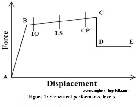
The performance based design process primarily requires that the expected performance objectives be clearly defined. These objectives correspond to a seismic hazard level and the expected performance levels of the structure. In other words, the level of ‘acceptable risk’ needs to be well defined. The ‘risk’ may be expressed in terms of seismic hazard and a susceptibility of structure to damage. The performance objectives are quantified can be called as ‘performance criteria’ which means a quantified acceptance criteria necessary to meet the performance objectives. In recent times, the performance objectives other than ‘Life Safety’, which was the major focus to reduce the threats to the life safety are also being considered. Such performance objectives may vary from ‘Collapse Prevention’ for the rare event of a large earthquake to an ‘Operational Level’ for frequent earthquakes of moderate size. The various performance levels along with their force-displacement characteristics are given below in Fig.1
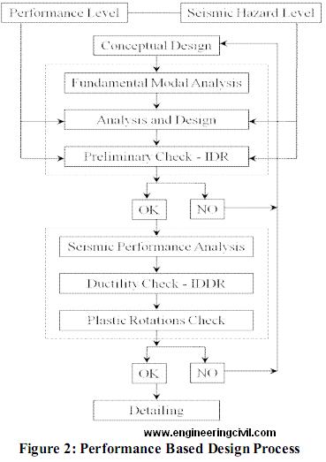
The Structural Engineers Association of California (SEAOC) in their Vision 2000 document defines the performance objective for buildings as the building’s expected performance levels, given a certain level of expected ground motions at a specific site to define the acceptability criteria for the structure. In general the fundamental process of PBD can be described using a flow chart shown in Fig.2.
3.0 ANALYSIS APPROACH:
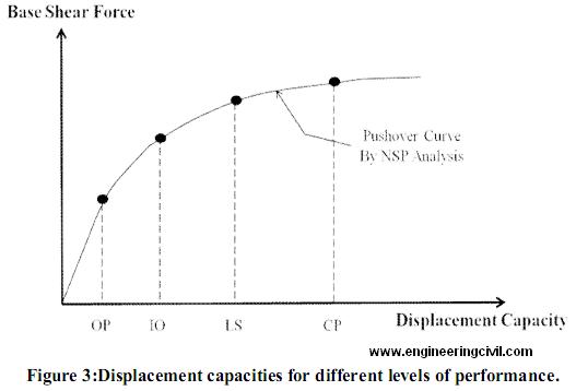
The inelastic displacements that the structure undergoes truly represent the damage sustained by the structure while dissipating the energy during an earthquake. Thus, the evaluation of displacement parameters for a given structure can provide a realistic evaluation of structural damage during earthquake. Nonlinear static pushover analysis is a simple tool that can be used for this purpose. It provides a ‘capacity curve’ of structure and relates the deformation parameters of the system (roof displacement) to the force parameter of the system (base shear). The displacement capacity of the structure goes on increasing with the increase of damage from ‘Operational’ to ‘Collapse Prevention’ level of the performance shown in Fig. 3
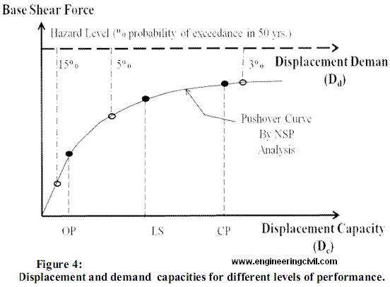
he displacement demands corresponding to various seismic hazard levels when combined with various performance levels, provides the information about the risk associated with a particular design. Fig. 4 represents the Displacement Capacities (Dc) corresponding to various performance levels and the Displacement Demands (Dd) for various hazard levels. When the displacement demands (Dd) are less than the displacement capacities (Dc) i.e. when Dc/Dd ratio is 1.0 or greater, then the performance objectives are achieved for such structures. In Fig. 4 if three performance levels OP, LS and CP are considered, then it is clear that the structure satisfies the performance objectives for OP and LS levels but fails to achieve the performance corresponding to CP performance level.
4.0 EXISTING CODE BASED APPROACH AND PERFORMANCE BASED APPROACH:
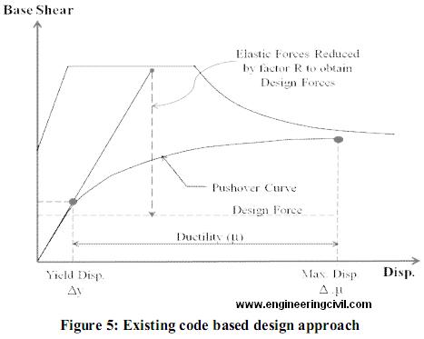
Initial design procedures considered that the earthquake forces acting on the structure are nothing but the inertial forces developed due to earthquake accelerations and thus would be proportional to the weight of the structure. Later, with the revolution in the design approach, wide range of studies on the actual behavior of structure resulted in shift to this procedure highlighting the fact that in addition to structure’s weight, the structural demands generated during the earthquake are the functions of its strength and stiffness properties. The existing conventional code based procedures are normative in nature. Such codes needs to cover a wide range of structures and thus, such codes usually cannot consider the various expected performance levels and seismic risk levels and are generalized. Performance based design on the other hand shows a major shift from such conventional normative codes and overcomes their limitations by considering both the performance and risk levels. In conventional code based procedures, design seismic forces for linear design are obtained by reducing an elastic demand by applying reduction factor ‘R’ which reflects the capacity of structure to dissipate energy through inelastic behavior. It is a combined effect of over strength, ductility and redundancy. The strength factor is a measure of base shear force at design level and at yielding. The ductility factor is a measure of roof displacement at yielding and at maximum target level. Redundancy factor depends upon the number of vertical resisting frames as defined by ATC-19 (see Fig. 5).
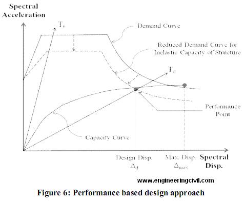
In performance based design on other hand, it is recognized that the inelastic seismic demands are based on the inelastic capacity of structure. As inelastic capacity increase, the period of structure lengthens; damping increases and demand is reduced. Capacity Spectrum Method gives a ‘Performance Point’ at which the displacement is consistent with the implied damping and the design is based on the displacement corresponding to the ‘Performance Point’ (see Fig. 6)
5.0 ILLUSTRATIVE EXAMPLE:
5.1 General:
The main objective of performance based seismic design of buildings is to avoid total catastrophic damage and to restrict the structural damages caused, to the performance limit of the building. For this purpose Static pushover analysis is used to evaluate the real strength of the structure and it promises to be a useful and effective tool for performance based design.
5.2 Description of structure:
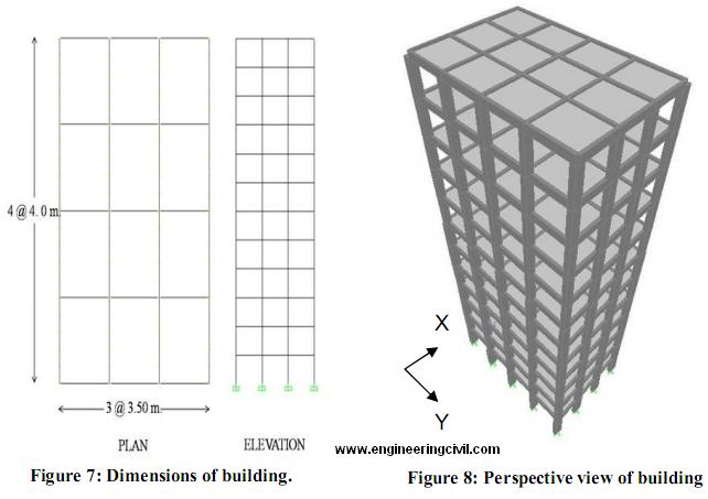
The building considered for analysis is a typical Ground+11 storey R.C. building designed as per IS 456 – 2000. The plan area of building is 10.5 x 16 m with 3.0m as height of each typical storey. It consists of 3 bays of 3.5 m. each in X-direction and 4 bays of 4. 0 m. each in Y-direction.
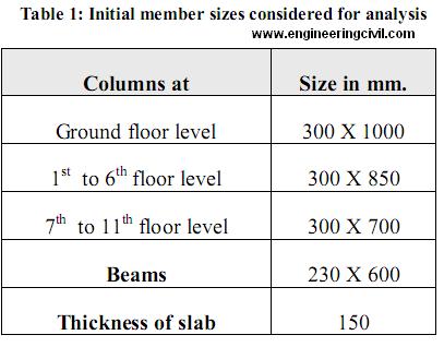
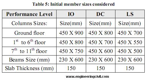
Material properties are assumed to be 20 MPa for the concrete compressive strength and 415 MPa for the yield strength of longitudinal and shear reinforcement. The sectional properties of various elements obtained based on gravity analysis and used as initial sizes for further analysis are presented in Table 1 below
5.3 Loading considered:
In the present example considered for illustration, all the floors of the building structure carries a dead load 4.75 kN/m2M/sub> and a live load of 3.0 kN/m2M/sub>, except for roof level.
The design lateral forces due to earthquake are calculated as per I.S. 1893:2002 (Part1). The seismic zone considered is zone-V with a factor (Z) 0.36. The importance factor (I) is 1.0 and the response reduction factor initially assumed to be 3.0.
5.4 Pushover Analysis:
Pushover analysis is an efficient way to analyze the behavior of the structure, highlighting the sequence of member cracking and yielding as the base shear value increases. This information then can be used for the evaluation of the performance of the structure and the locations with inelastic deformation. The primary benefit of pushover analysis is to obtain a measure of over strength and to obtain a sense of the general capacity of the structure to sustain inelastic deformation. The loads acting on the structure are contributed from slabs, beams, columns, walls, ceilings and finishes. They are calculated by conventional methods according to IS 456 – 2000 and are applied as gravity loads along with live loads as per IS 875 (Part II) in the structural model. The lateral loads and their vertical distribution on each floor level are determined as per IS 1893 – 2002. These loads are then applied in “PUSH – Analysis case” during the analysis.
5.5 Desired results from Pushover Analysis:
The performance of the structure is evaluated based on the results obtained from the pushover analysis. These are further described below.
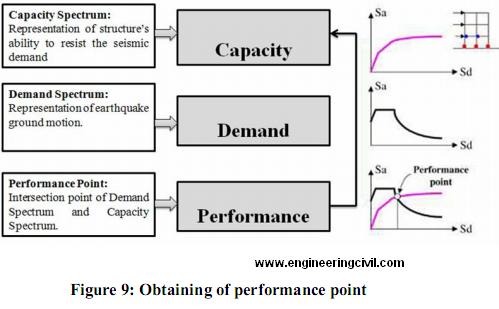
5.5.1 Determination of Performance Point:
The base shear Vs. roof displacement curve is obtained from the pushover analysis from which the maximum base shear capacity of structure can be obtained. This capacity curve is transformed into capacity spectrum ATC40 and demand or response spectrum is also determined for the structure for the required building performance level. The intersection of demand and capacity spectrum gives the performance point of the structure analyzed. This is illustrated in Figure 9. At the performance point, the resulting responses of the building should then be checked using certain acceptability criteria.
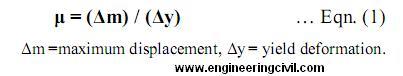
5.5.2 Displacement Ductility:
Ductility may be broadly defined as the ability of a structure or member to undergo inelastic deformations beyond the initial yield deformation with no decrease in the load resistance. The displacement ductility demand for a given earthquake load is obtained from the pushover curve and is calculated by the following equation,
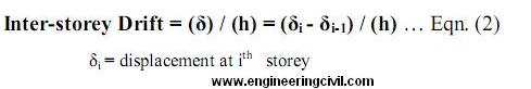
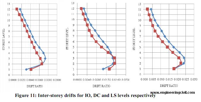
5.5.3 Inter-storey drifts:
Inter-storey drift is defined as the ratio of relative horizontal displacement of two adjacent floors and corresponding storey height (h).
Inter-storey drift is also one of the most important design parameters in all the seismic design codes as the performance of structural as well as non-structural components of a building is controlled by inter-storey drift. Inter-storey drift also controls the P-^ effects and governs the member sizes in many cases, particularly in tall buildings. I.S. 1893-2002 provides the drift control limit as 0.4% directly on the elastic displacement at the design load, without any amplification for ductility demand. ASCE 7 limits the total storey drift within 1.5-2.5% depending on the occupancy category for multistory RC frame buildings. For this reason, the guidelines given by FEMA-273 are followed in the present example for maximum allowable drift limits corresponding to various occupancy categories.
5.5.4 Ductility demand and plastic rotations:
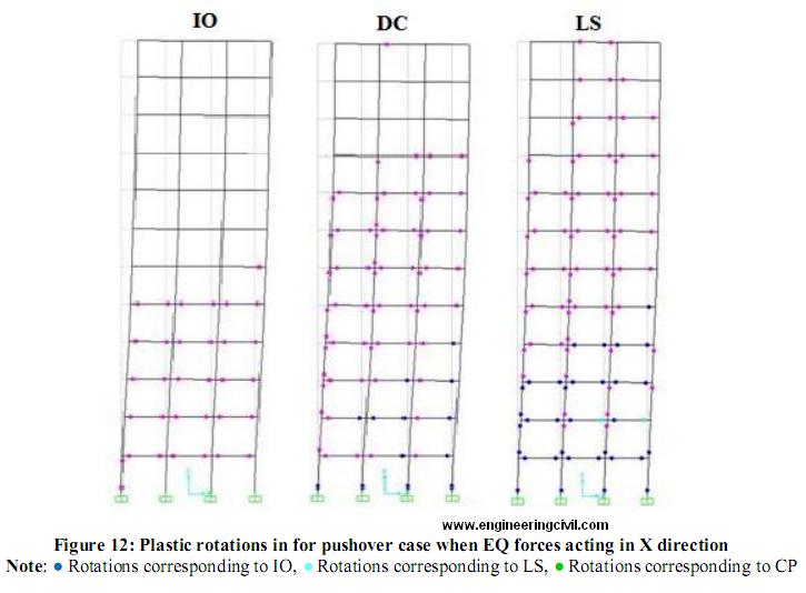
Ductility demands of the structure for various levels of performance can be expressed in terms of Inelastic Displacement demand Ratio (IDDR). IDDR represents the ratio of inelastic displacement demand over the ultimate inelastic displacement capacity. The sequence of plastic hinge formation and state of hinge at various levels of building performance can be obtained from SAP output. This gives the information about the weakest member and so the one which is to be strengthened in case of a building need to be retrofitted. Accordingly the detailing of the member can be done in order to achieve the desired pattern of failure of members in case of severe earthquakes.
5.5.5 Response reduction factor (R):
The response reduction factor or force modification factor R reflects the capacity of structure to dissipate energy through inelastic behavior. It is a combined effect of over strength, ductility and redundancy represented as:
R= RS X RR X Ru … (3)
where,
RS = Over strength factor
RR = Redundancy factor
Ru = Ductility reduction factor
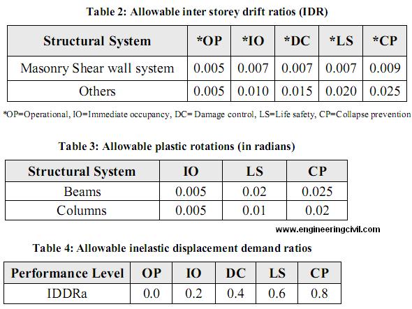
5.5.6 Acceptance levels (as per FEMA-273):
Following are the various allowable limits considered for deciding the performance levels of the structure, as given by FEMA-273.
5.6 Results:
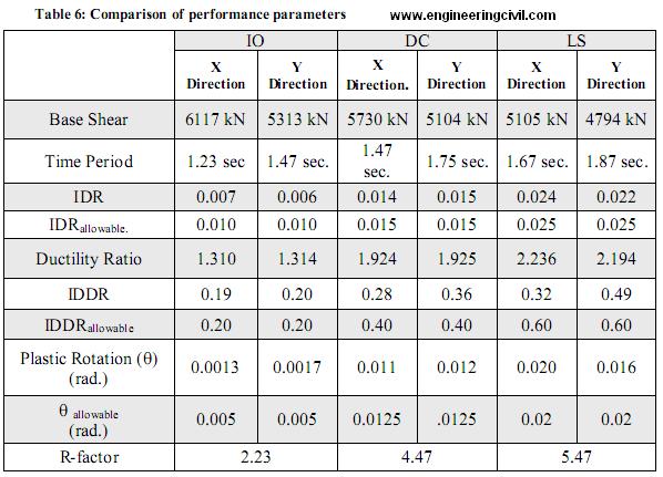
Based on the analysis performed for three different performance levels viz. Immediate Occupancy (IO), Damage Control (DC) and Life Safety (LS) the results are compared in terms of various performance parameters. For the purpose of analysis, modeling has been done using ‘SAP-2000’ software of Computers and Structures Inc. Following tables and figures indicates the comparison of these results.

5.7 Conclusions:
The fact that ductility of the structure has major contribution to response reduction factor for the structure highlights the importance of critical consideration of structural ductility in the seismic analysis process.
The response reduction factors for the various occupancy or performance levels have been computed with consideration of time period associated with each level. This overcomes the deficiency of adopting a constant reduction factor for all design periods.
The check for inter-storey ratios for each level of performance (as per the guidelines by FEMA-273), makes it meaningful so that the inter-storey drift is not limited to a value only at design load level and thus, it need not depend upon the ductility class of the structure.
The evaluation factors like displacement ductility, inelastic displacement demand ratio etc. justify the ductile detailing of the structure as every parameter associated with it is critically evaluated for the seismic behaviour at each performance level.
The determination of plastic rotations and the type of hinge formation for each performance level and their potential locations provides an useful input for providing special confining reinforcement in the structural members. The accuracy of this will depend upon the accuracy of modeling. Hence, it is necessary to establish proper guidelines or methodology for modeling in the respective seismic code, which also is the limitation of present Indian seismic code I.S. 1893-2002.
In the present paper, the possible performance based design methodology is described by consideration of very few variable parameters. Also, because of the limitation of not having some of the performance evaluation parameters in the present Indian seismic code, some of the guidelines given by FEMA-273 and others have been followed. To incorporate the performance based seismic design approach in the Indian
seismic codes, a comprehensive study is needed to decide such performance parameters which will suit the current design and construction practices in India.
5.8 References:
[1] ASCE, 2000, Pre-standard and Commentary for the Seismic Rehabilitation of Buildings, FEMA 356 Report, prepared by the American Society of Civil Engineers for the Federal Emergency Management Agency, Washington, D.C.
[2] ATC, 1997a, NEHRP Guidelines for the Seismic Rehabilitation of Buildings, FEMA 273 Report, prepared by the Applied Technology Council for the Building Seismic Safety Council, published by the Federal Emergency Management Agency, Washington, D.C.
[3] ATC, 2006, Next-Generation Performance-Based Seismic Design Guidelines: Program Plan for New and Existing Buildings, FEMA 445, Federal Emergency Management Agency, Washington, D.C.
[4] Bertero VV. 1997, Performance-based seismic engineering: a critical review of proposed guidelines. In: Proceedings of the International Workshop on Seismic Design Methodologies for the Next Generation of Codes. Bled/Slovenia.
[5] Mander J.B., 2001, Future directions in seismic design and performance-based engineering, Department of Civil Engineering, University of Canterbury, New Zealand, NZSEE 2001 Conference
[6] NEHRP, 2009, Research Required to Support Full Implementation of Performance-Based Seismic Design, prepared by The Building Seismic Safety Council of The National Institute of Building Sciences Washington, D.C.
[7] Newmark NM & Hall WJ. 1982. Earthquake spectra and design. Berkeley: Earthquake Engineering Research Institute.
[8] Peter Fajfar, M. EERI 2000. A Non Linear Analysis Methid for Performance Based Seismic Design Vol. 16, No. 3, pages- 573-592
[9] Qiang Xue, et. Al. “The draft code for performance-based seismic design of buildings in Taiwan”, Civil and Hydraulic Engineering Research Center, Sinotech Engineering Consultants Inc., Taiwan,2 October 2007.
[10] SEAOC, 1995, Vision 2000: Performance-Based Seismic Engineering of Buildings,Structural Engineers Association of California, Sacramento, California.
[11] T Paulay and N J N Priestley, Seismic Design of Reinforced Concrete and Masonry Buildings, John Wiley & Sons, 1992.
We at engineeringcivil.com are thankful to Sir Nilesh Kashid for submitting his research paper on “Performance based seismic analysis for buildings in India” to us. We are sure this will be of great help to all other engineers looking to study more in the field of seismic building analysis.
If you have a query, you can ask a question here.
the paper is very much informative.could you suggest any software to do the push over analysis.