By
Ghalndarzadeh A., Akbari N., Fakher A. from University of Tehran
ABSTRACT
Seismic behavior of quay walls is one of major concerns in earthquake geotechnical engineering field. Among different types of quay walls such as caisson and concrete block walls, deck and pile structures and anchored flexible walls the behavior of flexible walls looks more complicated. In the presented research, a series of shaking table tests were carried out in order to understand the seismic behavior of anchored flexible quay walls. The models were fully instrumented to monitor their behavior during shakings. Displacement of the wall, accelerations in the backfill, excess pore pressures in the soil, bending moment in the wall and tension of tie-rods were measured. By making different relative densities for the backfill and the foundation, different failure modes were observed. It is concluded that the performance of an anchored quay wall is strongly influenced by the occurrence of liquefaction.
Keywords: Anchored flexible quay wall, liquefaction, softening, failure modes
NTRODUCTION
Relatively poor performance of quay walls during recent earthquakes is the reason for recent changes in design philosophies and guidelines. However, very complicated seismic behavior of quay walls shows that investigation in this field did not reach to its end and new researches is necessary. The main types of quay walls are the gravity type, such as caisson and concrete block walls, deck and pile structures and anchored flexible walls. Seismic behavior of anchored flexible quay walls is not fully understood because of the complicated behavior of walls, anchors and tie-rods in addition to the possible strength degradation of backfills. If a layer of the backfill liquefies during an earthquake, the prediction of the quay wall behavior would be very difficult because of the unknown soil pressure and softening of soil.
In order to understand the effect of extent of a liquefiable layer in backfill area a series of shaking table tests were carried out on model anchored flexible quay walls. Testing procedure, instrumentation, recorded results as well as some important observations are described in this paper.
INSTRUMENTATION
The investigations described in this paper were conducted using shaking table facilities of university of Tehran. Materials, devices, transducers are used in this study are described in the following parts.
Test box and shaking table:
The shaking table is made of two boards fixed together with three vertical steel plates. The excitation is induced horizontal movement and the vertical plates make a uniform sinusoidal dynamic acceleration on the model. The soil box is 184cm long, 50cm wide and 75cm deep made of a 2cm thick transparent Plexiglas which is set over the shaking table. In order to isolate the saturation system so preventing any sand entering the water and CO2 entrance paths, the bottom of the soil box is covered with a layer of No.100 screen mesh.
Transducers and data acquisition system
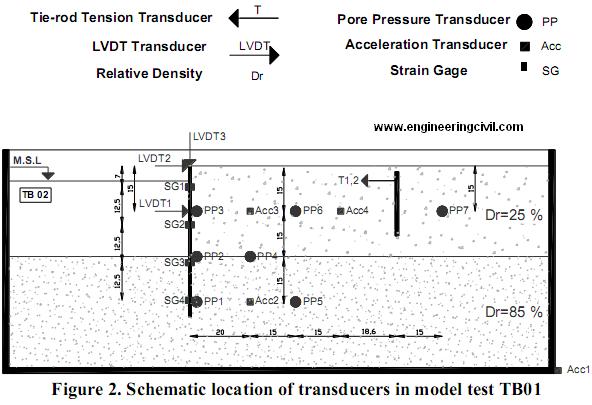
As shown in figure 2, five types of transducers are used in this study to monitor the displacements, accelerations and pore pressures, bandings and forces. The pore pressure transducers are fixed in place, but the acceleration transducers are free and can vibrate with the adjacent soil easily. Strain gauges are fixed to flexible model wall so that be able to measure bending deformation of model wall. In addition a suitable load cell is used to measure the tension load of tie rods. A 20 channel dynamic data acquisition system is also used to measure dynamic response of model wall. The analogue signal from the transducers is taken at predetermined sample rate of 100 samples per second for each channel, and then digitized by an Analog-to-Digital converter. The digital data are stored and processed by a personal computer.
SOIL PROPERTIES
Oven-dry Firuzkooh silica sand was used throughout this study. The typical properties of the above sand are shown in table 1 which can be compared to those of Toyoura sand and Sengenyama sand. All tests during this study were carried out on the above sand with different average densities.
Table 1. Properties of Firuzkooh sand and comparison with two other sands

RETAINING WALL SYSTEM
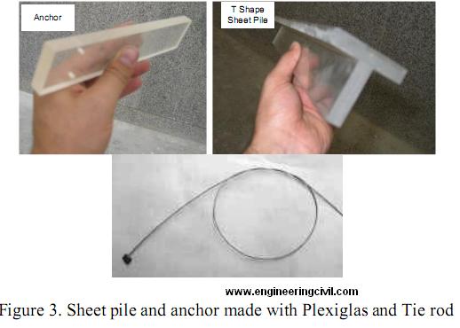
The retaining system consists of a series of sheet piles and anchors made with Plexiglas and also tie- rod made of steel cable. Fig.3 shows these elements. Sheet piles have a T shape cross section. The models were designed based on real quay walls of new development of Shahid Rajaee port in southern Iran. The original walls were to be made of reinforced concrete. The selected sizes and materials were selected using suitable scaling factors. However the objective of the current study is only to observe the mechanisms that govern the seismic behavior of flexible type quay walls.
MODEL PREPARATION
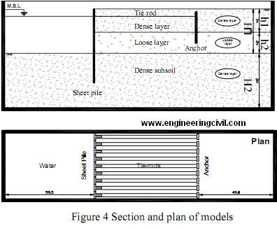
Making controlled loose to dense deposit is possible using the wet tamping method; hence the Firuzkooh sand was mixed with 5% water. Wet Firuzkooh sand was poured inside the container and carefully tamped to the target void ratio. To observe the overall deformation of the foundation soil and backfill soil square grids of dyed sand was installed in the sandy fill. Since the grid consisted of the same material as the model foundation soil, it easily moved together with the model without bending, floating, or subsidence. Construction of models was continued by placing all components including T shape walls, anchors, tie rods and transducers. Then the soil models are percolated with carbon dioxide to help dissolve the air in the void space, in order to facilitate full saturation by water. The saturation process is performed by injecting water gradually from the bottom of the soil box. Plan and section of model is shown in Fig.4. As it is shown in this figure total numbers of nine T shape elements, nine anchor elements and eighteen tie-rods were used in each model. To study the effect of liquefiable layer in backfill area a loose layer was placed with different thickness in different tests.
TESTING
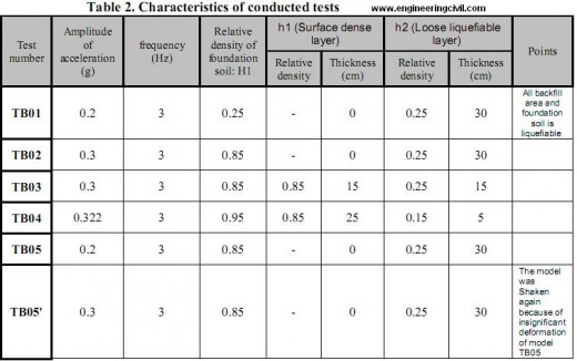
Five different models were constructed in this study. The important feature of these models is the use of different thickness of a liquefiable layer in backfill area. Table 2 summarizes information of these model tests. The main differences between these tests were different thickness of liquefiable layer as well as different intensity of input motion. Test TB5 was similar to test TB2 but with different level of input acceleration. However, because of no visible deformation it was shaken with larger input acceleration as the secondary test TB5’. Variation of liquefiable and non-liquefiable layer is shown by h1 and h2.
The shaking was a harmonic horizontal-longitudinal motion with variety of acceleration amplitudes. The base shaking frequency was 3 Hz and the model was shaken for 10 seconds in all tests and the data of sensors were recorded for 40.96 seconds.
RESULTS AND OBSERVATIONS
The recorded data and its interpretations to show the model behavior is presented in this part. The observed deformation patterns and failure mechanisms are also described. Effect of different parameters on the observed behaviors is also discussed.
General results
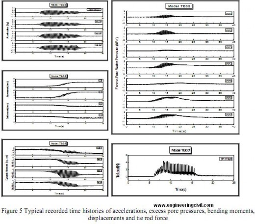
Time histories of input and response accelerations, excess pore water pressures, bending moment, displacements and tie rod force are recorded. Figure5 shows the results of test TB05 as a sample. Change in accelerations recorded in different points that is due to dynamic ground response is obvious. This change is also was observed in all other tests. Moreover, excess pore pressure is quite different in different locations. Intensity of input shaking as well as relative density of ground could change the pore pressure response. This will be discussed later in detail. Other aspects of model response can be seen in figure5.
Observed failure mechanisms
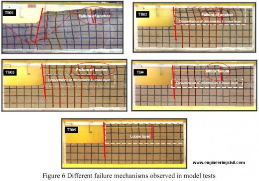
Different observed failure mechanisms and displacement modes are shown in figure 6. A total failure of backfill and foundation soil is visible in test TB01. As it is mentioned in Table 2 both backfill and foundation soil were loose with a relative density of 25%. Extensive loosening of soil was observed in both areas due to increase of excess pore pressure. This situation caused a large displacement of sheet pile wall. The displacement mode appeared in a rotation form and a large deformation that indicates a serious failure. As it is shown in figure 6 the anchor has suffered a large displacement that means this supporting system did not work at all. On the other hand there was not any sign of resistant in embedded area of sheet pile.
When the foundation soil was dense that is the case in test TB02 the failure mechanism was changed. As it is shown in figure 6 displacement of the wall was considerably decreased in this test. In contrast to test TB01, the quay wall experienced an overturning the indicated more resistant in the embedded part and almost no resistant of anchor system. However displacement was smaller than that of test TB01. It should be noted that in test TB01 the input acceleration was 0.2 that is less than that of test TB02.
In test TB03 a loose layer with thickness of 15 cm underlies a 15 cm dense surface layer. Interestingly the quay wall has experienced even larger displacement compared to the test TB02. Although minor failure is observed in the anchor area, there is larger deformation in intermediate loose layer. However, with reducing the thickness of loose layer from 15 cm in test TB03 to 5 cm in test TB04 deformation has been controlled to some extent. As mentioned in Table 2 tests TB02 and TB05 are similar but with different intensity of input acceleration. The failure mechanism is not change in test TB05, however the displacement of quay wall was smaller.
Effect of excess pore pressure on failure of quay wall
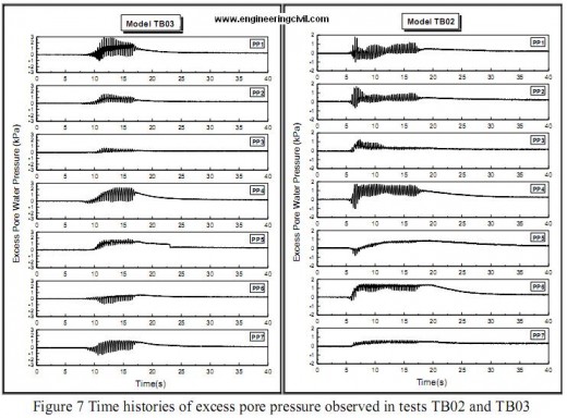
Different failure mechanisms explained in the previous part seems to have relation with the softening of foundation soil, backfill and the soil surrounding the anchor. It is well known that this type of softening is mainly due to build up excess pore pressure caused by seismic load. To explain the observed failures and their differences, recorded pore pressures are assessed here. Figure 7 illustrates excess pore pressure histories in tests TB02 and TB03. As it is shown in this figure maximum pore pressure recorded by PP4 and PP6 transducers in test TB02 are higher than those of test TB03. The same comparison between pore pressures of PP2 and PP3 indicates similar trend. It should be noted that backfill soil in test TB02 was looser than test TB3. The number of cycles to achieve the maximum pore pressure is greater in test TB03. By increasing the thickness of dense layer, rate of pore pressure build up as well as its maximum value decreased.
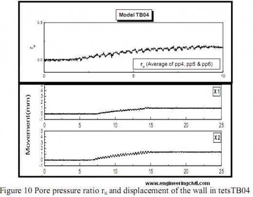
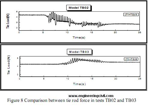
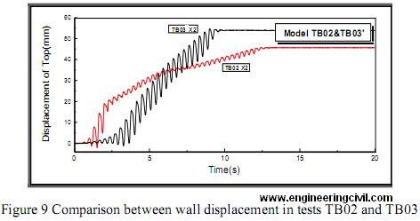
The transducers PP6 and PP7 were in front and back side of anchor respectively. Higher pore pressure in this region in test TB02 agrees with the observation of larger damage of anchor in this test. Figure 8 shows tie rod forces in test TB02 and TB03. It can be seen that in test TB02 tie rod force decreased after the base motion was applied. Whereas in test TB03 the trend was reverse and tie rod has increased. This shows that anchor system could resist against the wall movement and was effective when the backfill soil was denser. However, figure 9 shows that the displacement of sheet pile did not decrease in test TB03. This looks strange because with a densified backfill reduction of wall displacement was expected. It seems although the anchor showed some resistance, the large deformation of loose layer under the dense surface layer did cause the large displacement of 1uay wall. It seems the performance of quay wall depends not only on the resistance of anchor system but also to the thickness of the dense surface layer. This fact can be clearly seen in Figure 10 that shows the displacement and pore pressure ratio histories in test TB04. In this figure pore pressure ratio denotes the ratio of excess pore pressure to the effective initial stress. It can be observed that the pore pressure ratio was too small and displacement of the model wall was considerably smaller than before. It seems increasing the thickness of dense surface layer could control the wall displacement. This observation can be used to decide how much depth of backfill should be improved.
As a countermeasure method densification of surface layer could be a choice. Dynamic compaction can influence different depths to reduce liquefaction potential of the soil. Depending on the thickness of improved layer seismic displacement of anchored flexible quay walls can be reduced. It is very important to note that if the thickness of improved layer is not sufficient, this method will not be effective. In fact it can be concluded that existence of a liquefiable subsurface layer could cause failure of the quay wall. This means that a careful study on dynamic compaction should be done or other methods should be employed for deeper improvement.
CONCLUSION
The followings are the conclusions of the current study.
– Failure mechanisms and different deformation modes are observed in the conducted model tests. It was observed that when the backfill as well as foundation soil were loose the model wall has experienced a large movement. Neither embedded part of quay wall nor the anchorage system could resist against large displacement of the wall.
– With a dense foundation soil the wall displacement has decreased however extensive loosening of the backfill has exerted a large earth pressure to the model quay wall increasing the bending moment of the wall and relatively large displacement of the head of quay wall. There was no resistance of anchor because of failure of nearby soil due to increase of excess pore pressure.
– Making a dense layer above the loose backfill with a thickness of half height of the wall was selected to reduce the wall displacement. Interestingly this thickness of the densified layer not only did not decrease the wall displacement but it caused a larger displacement. It was observed that the underlying loose layer deformed due to increase of excess pore pressure and has caused larger wall displacement. The force recorded in tie rod indicated the effect of anchor. However it was not able to stop wall displacement.
– By increasing the thickness of surface dense layer the wall movement as reasonably decreased. It may suggest that any improvement applied on the backfill soil should be deep enough. Otherwise it will not decrease or stop the quay wall failure.
– The above explanations are in good agreement with the recorded excess pore pressures, displacements and tie rod resistances.
REFERENCES
Gazetas, G., Dakoulas, P. and Dennehy, K., “Empirical Seismic Design Method for Waterfront Anchored Sheetpile Walls”, Proceedings of ASCE Geotechnical Special Publication No.25, 232-250, 1990
Ghalandarzadeh A, Towhata I, Momeni SO. “Shaking induced water pressure acting on walls.” Publications Committee of the XV ICSMGE, Editor. Proceedings of the 15th International Conference on Soil Mechanics and Geotechnical Engineering, Istanbul, Turkey. Lisse: Balkema,
2229-32, 2001
Ghalandarzadeh A, Towhata I, Takashi O. “Shaking table tests on seismic behavior of quay walls subjected to backfill liquefaction.” Geotechnical Earthquake Engineering and Soil Dynamics Conference ASCE, Seattle, May 1998.
Ghalandarzadeh, A., Orita, T., Towhata, I. and Young, F., “Shaking Table Tests on Seismic Deformation of Gravity Quay Walls”, Soil and Foundation, Special Issue on Geotechnical Aspects of January 17 1995 Hyogoken Nambu Earthquake, 2,115-132, 1998
Ghalandarzadeh, A., Sadrekarimi, A., Momeni, S.O., “Facrors Affecting Shaking Induced Water Pressure Behind Quay Walls”, 13th World Conference on Earthquake Engineering, Vancouver, Canada, 2004
Iai, S., “Similitude for Shaking Table Tests on Soil-Structure-Fluid Model in 1g Gravitational Field” soil and Foundations, JSSMFE, 29(1),105-118, March 1989
Iai, S., Ichii, K., “Excess Pore Water Pressure Behind quay walls”, Proceedings of ASCE Geotechnical Special Publication No.64, pp.11-25, 1997
Kramer, S.L., “Geotechnical Earthquake Engineering” Prentice Hall, 1996
Nason J. McCullough,1 S.M., ASCE, and Stephen E. Dickenson, A.M., “Estimation of Seismically Induced Lateral Deformations for Anchored Sheetpile Bulkheads”, of Geotechnical Earthquake Engineering and Soil Dynamics III. Held August 3-6, Seattle, WA, USA. pp 1095-1106, 1998.
PIANC, “Seismic Design Guidelines for Port Structures”, Balkema, 2001.
Seismic Behavior of Flexible Retaining Systems Subjected to Short-Duration Moderately Strong Excitation” Soil Dynamics and Earthquake Engineering, pp.537-550, 2004
Steedman , R.S., & Zeng, X., “The Seismic Response of Waterfront Retaining Walls, Design and Performance of Earth Retaining Structures, Geotechnical Special Publication, No.25, ASCE, pp.872-886, 1990
Towhata I, Ghalandarzadeh A, Prasad SK, Vargas-Monge W. “Dynamic failures observed in water front areas.” Special Issue of Soils and Foundations, 149-60. 1996
Zeng, X., “Seismic Response of Gravity Quay walls I: Centrifuge Modeling”, Journal of Geotechnical and Geoinviromental Engineering, pp.406-417, 1998]
We at engineeringcivil.com are thankful to Er Ghalndarzadeh A., Akbari N., Fakher A. for submitting the research paper of “Liquefaction Investigation On Sea Walls By Shaking Table Tests” to us. We are hopeful that this will be of great significance to all those who are willing to understand and know more about the impact of Liquefaction on Sea Walls.
If you have a query, you can ask a question here.


