

AIM OF THE EXPERIMENT:
To determine the undrained shear strength of a sandy to silty soil.
CODE OF REFERENCE:
• IS 2720 (Part 13)- 1986 Methods of test for soils: (Part -13) Direct Shear Stress
• IS 2720 (Part 2)- 1973 Methods of test for soils: (Part -2) Determination of water content
APPARATUS USED:
- Loading frame
- Weights
- Proving ring
- Micrometre Dial- Gauges
- Sample trimmer or core cutter
- Stop clock
- Balance
- Spatula and a Straight Edge
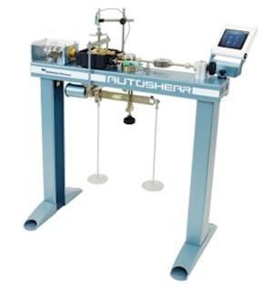
Fig 1: Direct Shear Test apparatus
COURTESY: GEOENGINEER.ORG
SOIL SPECIMEN:
Undisturbed specimen- Specimen of required size shall be prepared in accordance with IS 2710 (Part-1)- 1983.
REMOULDED SPECIMEN:
a) Cohesive soil may be compacted to the required density and moisture content, the sample extracted and then trimmed to the required size. Alternatively, the soil could also be compacted to the specified density and moisture content directly within the shear box after fixing the two halves of the shear box together by the means of fixing screws.
b) Cohesionless soil may be taped in the shear box itself with the base plate and grid plate or porous stone as required in place at the bottom of the box.
The cut specimen shall be weighed and trimmings obtained during the cutting shall be used to obtain the moisture content. Using this information, the majority dry density of the specimen within the shear box shall be determined.
THEORY
The direct shear test is one among the oldest strength tests for soils. In this laboratory, a direct shear test device will be used to determine the shear strength of a cohesionless soil (i.e., angle of internal friction (ɸ). From the plot of shear stress verses the horizontal displacement, the maximum shear stress is obtained for a specific vertical confining stress. After the experiment is run several times for various vertical confining stresses, a plot of the utmost shear stress verses the vertical (normal) confining stress for every of the tests is produced. From the plot, a straight-line approximation of the Mohr – Coulomb failure envelope curve can be drawn, ɸ may be determined, and for cohesionless soils (c=0), the shear strength can be computed from the following equation:
τ = σ tanɸ
RELEVANCE OF THE EXPERIMENT:
- This test is performed to determine the undrained shear strength of a sandy to silty soil.
- Shear strength is evaluated with the help of this test of a cohesionless soil.
- This provides an important engineering property of a soil, because it is required whenever a structure is dependant on the soil’s shearing resistance.
- This helps in good engineering situations like determining the stability of slopes or cuts, finding the bearing capacity for foundations and calculating the pressure exerted by soil on a retaining wall.
- If this is not evaluated, engineering problems will arise such as in design of foundation, retaining walls, slab bridges, pipes, sheet piling, etc.
PROCEDURE
- The portion is fit into shear box with the help of specimen, plain grid plate over the base plate at the bottom of the specimen and plain grid plate at the top of the specimen in the load frame.
- The loading pad is placed on the top grid plate. The vessel should be provided in order that the sample doesn’t get dried during the test.
- The required nominal stress is applied and the rate of longitudinal displacement/ shear displacement is adjusted so that no drainage can occur in the sample during the test.
- The upper part of the shear box is raised such that a gap of about 1mm is left between the two parts of the box.
- The horizontal shear load to failure is applied or to 20 percent longitudinal displacement whichever occurs first.
- The shear readings indicated are noted by the proving ring assembly and the corresponding longitudinal displacement at regular intervals.
- If necessary, the vertical compression, if any, of the soil specimen my be measured to serve as a check to ensure that drainage has not taken place from the soil specimen.
- At the end of the test, the specimen is removed from the box and the final moisture content is measured.
- The specimen of same density is at least tested three times.
OBSERVATIONS AND RESULTS
- Proving ring (stress gauge) constant = kg/ division.
- Dial gauge (strain gauge) constant = mm/ division.
- Deformation rate = mm/ minute.
- Shear box size = cm3
- Area of shear box = cm2
- Normal stress = kg/cm2
TABLE 1
| Displacement dial reading | Displacement, d (mm) | Area correction (mm2) | Corrected Area, Ac = A0 (1-d/3) | Stress dial reading | Shear force (N) | Shear stress (N/mm2) |
| 0 | 0 | |||||
| 20 | 0.2 | |||||
| 40 | 0.4 | |||||
| 60 | 0.6 | |||||
| 80 | 0.8 | |||||
| . | . | |||||
| . | . | |||||
| . | . |
TABLE 2
| Normal stress (kg/cm2) | Shear stress at failure (kg/cm2) | Cohesion intercept | Angle of shearing resistance |
RESULT AND DISCUSSION
The cohesion intercept and angle of shearing resistance are determined plotting graph between shear stress at failure and normal stress. This test is simple and fast for sands. The sample is normally saturated before the test is run. For this experiment we use clean sand as a sample so there is no problem as the pore pressure dissipates readily. However, in case of highly plastic clays, it is merely necessary to have suitable strain rate so that the pore pressure can dissipate with time. Direct shear test is useful when cohesionless soil are to be tested. In case of cohesive soil drainage time will be more and there is no control over drainage as in case of triaxial test hence it is suitable for sandy soils.
REMARKS
- The result is obtained as per IS code. The soil specimen was taken as per IS 2720 (Part 1)-1983.
- The condition of machine also impacts on results. If machine is old then results might vary. Plus, the weights might have wrongly placed or misplaced.
- Soil should be compacted properly in three layers. The shearing should be tightly fixed while compacting. While placing the shear box, the shearing pin should be removed. The readings of proving ring dial gauge reading should be taken.
- This test is simple and fast to operate. As thinner specimens are used in shear box, they facilitate drainage or pore water from a saturated sample in less time. This is useful to study friction between two materials.
- Another advantage is that apparatus is cheaper and no technical skill is required to operate it.
- One disadvantage involves that there is no mechanism to measure pore water pressure hence this is not for fine grained soils.
If you have a query, you can ask a question here.