

Introduction
Ground Improvement in its broadest sense is the alteration of any property of a soil or rock to improve its engineering properties. This may be a permanent measure to improve the completed facility or a temporary process to allow the construction of a facility. Various processes of ground improvements are available to increase the strength, reduce compressibility, reduce permeability, or improve groundwater conditions. Further, if there is any foundation distress in the existing structures, in-place foundation treatment can be applied to rehabilitate the structure. The techniques involved in the attainment of the required improvement facilities are referred to as geotechnical processes.
Ground Improvement Techniques may be classified based on the nature of the process involved; the material used, the desired results, etc. Various techniques used are compaction, drainage methods, pre-compression, and vertical drains, vibration methods, grouting, and injection, mechanical, cementing and chemical stabilization, geosynthetics, and miscellaneous methods.
The factors that must be considered in the selection of the best technique, in any case, include the following
- Type of soil i.e., clay, organic, sandy
- Area and depth of treatment required- depending on the geometric characteristics of the soil deposit and the nature of facilities proposed for construction.
- Type of structure and load distribution. Soil properties like strength, compressibility, permeability, etc.
- Availability of materials- stone, sand, water, admixture, stabilizer, etc.
- Availability of skills and equipment.
- Environmental considerations- waste disposal, erosion, water pollution, etc.
- Local experience and preferences.
Compaction
It is essential that in place soil should possess certain properties to withstand the load caused by the structure. Soil should have adequate strength, bearing capacity, should be capable to resist settlement, should possess proper permeability and drainage, and should be safe against deterioration. These desirable features can be achieved by compacting in-place soil or by providing compacted fill with suitable soil. Soil can be compacted by applying compaction energy in the form of pressure (rolling), impact or ramming, or vibration.
Densification may occur in several ways such as re-orientation of particles. For a cohesive soil, densification is primarily attained by distortion and re-orientation which are resisted by inter-particle forces.
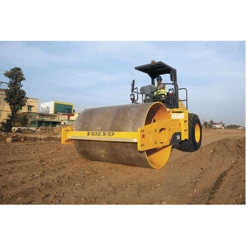
Fig 1: Vibratory soil compactor
Compaction is measured quantitatively in terms of dry density. The maximum dry density varies from about 22 kN/ for well-graded gravel to about 14 kN/ for heavy clay. Dry density can be obtained in laboratory tests or the field with any soil depends upon its type. There are two laboratory Compaction tests:
- Standard Proctor Test (IS: 2720-Part 7)
- Modified Proctor Test (IS:2720-Part 8)
Various types of equipment are used on the surface of the ground to improve material properties to a limited depth from the ground surface.
Static compaction rollers and compactors may be classified as
- Towed static smooth compactors.
- Static sheep’s-foot or pad-foot compactors.
- Static three-wheeled self-propelled compactors.
- Static tandem compactors.
Vibratory compactors may be categorized into the following groups:
- Tandom vibratory compactors.
- Towed vibratory compactors.
- Towed sheep’s-foot or tamping-foot vibratory compactors.
- Self-propelled vibratory compactors.
- Hand-guided vibratory compactors.
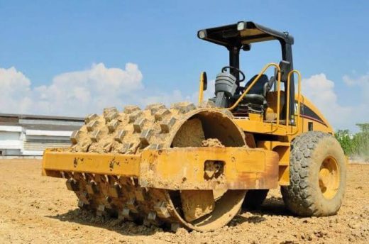
Fig 2: Sheep’s-foot roller
Dynamic Compaction
In this method, a very heavyweight about 45000 kg is dropped from a height of 15 to 40 meters to fall freely back to the ground surface. Due to the impact energy on the cohesionless soils cause liquefaction of the area. It is followed by settlement due to rapid drainage. This process is then repeated either at the same location or subsequently on other location by keeping a spacing of 5 to 10 meters. After allowing the required numbers of drops, the area will be stabilized or compacted at a certain depth. This depth is known as depth of compaction. The range of energy per blow is 135000 to 450000 kg m. Generally, total tamping energy of 2 to 3 blows per sq. m. is used. Efficiency is increased if the impact velocity exceeds the wave velocity in a liquefying soil.
The advantages of dynamic compaction are-
- It is one of the simplest and most suitable methods of compacting loose soils.
- Here, the depth of compaction can reach up to 20 meters.
- With this method, all types of soils can be compacted.
- This method produces equal settlements more quickly than surcharge type loading.
- It can be used to treat soils both above and below the water table.
Drainage methods
In any civil engineering construction, groundwater is usually considered as one of the most difficult problems that have to be handled. It is necessary to eliminate the seepage pressure to increase the shearing resistance or to reduce the danger of frost damage. Dewatering systems and drains are the two important methods that are used to improve the ground condition before and after construction.
Dewatering systems consist of lowering the water table to a required elevation and to establish below this level a system of collectors located in wells, galleries, or ditches. The waters are pumped from the water collectors. Again continuous pumping from the natural ground is a costly affair and the continuous flow from the surrounding ground may endanger the stability of the adjacent structure. On the other hand, drains are provided to serve for controlling the flow; in some cases lowering the water table helps in reducing pore water pressure and seepage forces.
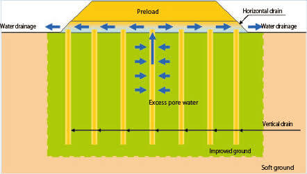
Fig 3: Vertical drainage system
In any drainage system, perforated pipes and conduits having perforations with open points are provided. The space between natural soil and the pipe is filled with fillers. In general, a filter or a draining material should satisfy the following requirements:
- The gradation of the filter material should be capable of forming small size pores such that migration of adjacent particles is prevented.
- The gradation should allow rapid drainage without developing a large seepage force.
There are various methods of dewatering systems. For example; open sumps and ditches, wellpoint systems both single-stage and multistage wellpoint systems, deep well drainage, vacuum dewatering systems, and dewatering by electro-osmosis.
Precompression
Precompression is the technique applied on the ground to improve the subsoil condition by applying temporary loading at the construction site. It can be done with or without the use of vertical drains. Precompression is also referred to as preloading. Preloading has been used in many civil engineering works such as road embankments, bridge abutments and box culvert warehouses, gravity quay walls, runways, storage tanks, etc. preloading methods have several advantages:
- The cost involved is comparatively less.
- The fill material after completion of preloading can be used as fill material for the next project or site preparation.
- Simple and conventional construction equipment is sufficient for preloading works.
- Cost of monitoring instruments is cheap.
- It provides uniform improved properties of the ground.
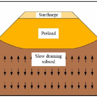
Fig 4: Precompression or preloading
Vertical drains
Preloading techniques are likely to be inefficient when used alone in very thick soft clays of the soils with low permeability. Because a long time is needed for a significant compression. The length of the drainage path should be short as the drainage path controls the time of consolidation. Radial improvements in preloading time can be affected by the installation of vertical drains to shorten the drainage path under which clay will consolidate.
Vertical drains are continuous columns of pervious material like sand or fibrous material installed in clayey soil. The drains provide the pathway for the pore water to escape from the consolidating soil. There are two types of vertical drains. Sand drains and prefabricated drains. The drains are installed by
- High-pressure water jetting
- Displacement of the natural ground
- Wash boring
Vibration methods
Vibration methods are used in any ground improvement techniques which could bring in deformation and displacement resulting in densification. Cohesionless soils get densified largely by fracture and reorientation of the grains. Static forces are not effective in this process. Different types of vibration methods are Vibro-compaction, Vibro-displacement compaction, Vibroflotation, etc.
The Vibro-compaction method is effectively used in the densification of saturated cohesionless soil. In this method, vibration or shock waves are given in loose soil deposits which cause localized spontaneous liquefaction followed by densification and settlement. The load due to shock is temporarily transferred to the liquid and then soil particles take a much denser pattern. The new density and compactness attained by this process is permanent and irreversible.
In Vibro-displacement compaction method, vibrations are supplemented by active displacement of soil and by backfilling the zones from which the soil has been displaced.
Vibro-flotation is an efficient technique for densifying cohesionless soil with simultaneous vibration and saturation. The Vibro-flotation equipment comprises a vibroflot probe, accompanying power supply, water pump, crane, and front-end loader.
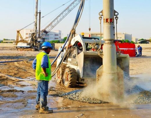
Fig 5: Vibro-flotation technique
Stone columns
It is also called granular piles. Stone columns are installed mostly by vibration techniques. A cylindrical vertical hole is made first and gravel backfill is placed into the hole in increments and compacted radially. This results in a densely compacted stone column of a certain depth and diameter. Stone columns may be arranged to support isolated footings, strip footings, or mat foundations. The entire foundation area should be covered with a blanket of sand or gravel at least 0.3 meters. It helps to distribute loads uniformly and to facilitate drainage of water conducted out of the soft soil through columns which act as vertical drains as well as reinforcing elements.
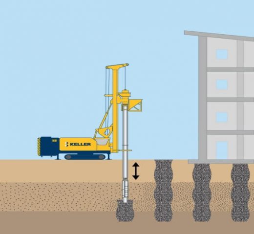
Fig 6: Stone column
Grouting and injection
It is a process of ground improvement which is attained by injecting fluid-like material into the subsurface of soil or rock. Grouting is valuable in foundation work before construction, during construction, and after construction. Before construction grouting is used to control water problems, infill voids, to control settlement, and to increase soil bearing capacity. During construction, grouting is used to control groundwater flow to stabilize loose sand against liquefaction, to provide adequate lateral support and after construction, it is used to reduce machine foundation vibrations and to eliminate new seepage.
Three types of grouting are there. In Permeation or penetration grouting where the grout flows freely with minimal affect into the soil voids or rock seams. In Compaction or controlled displacement grout remains more or less intact as a mass and exerts pressure on the soil or rock. In Hydraulic fracturing grouting grout rapidly penetrates into a fractured zone which is created when the grouting pressure is greater than the tensile strength of the soil or rock being grouted.
All types of grouts are used including cement, cement and sand, clay-cement, slag-cement, resin gypsum cement, clays, asphalt, pulverized fuel ash (PFA), and a large number of colloidal and low viscosity chemicals.
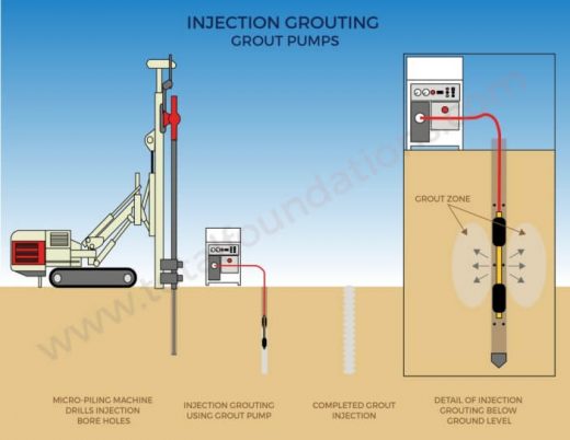
Fig 7: Injection and Grouting
Geosynthetics
Geosynthetics are artificial fabrics used in conjugation with soil or rock as an integral part. Two major types of geosynthetics are geotextiles and geomembranes. Geotextile is a permeable fabric while geomembrane is an impermeable one. The functions of geosynthetics are separation, fluid transmission, reinforcement, filtration, containment, and barrier. Geosynthetics can be sub-divided into the following groups, viz, Woven, Non-woven, Knitted, biodegradable, Nets and Grids, three-dimensional Mats, Composites, and Membranes.
Geosynthetics are also used as filters in riverbank protection works, downstream culverts, and in bed protection works along canals.
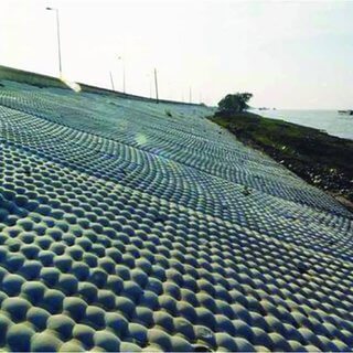
Fig 8: Geosynthetics used in River Bank Protection
If you have a query, you can ask a question here.