

By
Shri.Pravin B.Waghmare
Lect. In Civil Engg. Dept.
Acharya Shrimannarayan Polytechnic, Pipri (M)
Wardha (MH)-India
Abstract
Liquid storage tanks are important components of lifeline and industrial facilities. They are critical elements in water supply scheme and fire fighting system, and extensively used for storage and processing of variety of liquid like material such as petroleum product, liquefied natural gas, chemical fluid and wastage of different forms. In this paper, the seismic response of base isolated cylindrical liquid storage tanks is investigated under real earthquake ground motion. The isolation systems considered is elastomeric bearings (without lead core), the specific objectives of the study are to carry out the comparative performance of the tanks with isolation and without isolation (i.e. Fixed tanks) also to investigate the response of the tanks for varying capacity with varying heights. For this study forty tanks of varying heights such as 8m,10m,11m,11.5m,12.5m,14m,16m with varying capacities of 500kl, 265kl, 200kl, 100kl, 50kl are considered. For this a time history analysis has been carried out by using a three time history of varying magnitude with varying peak ground acceleration. It is observed that the base shear of elevated liquid storage tanks supported on shaft is significantly reduced due to isolation. The drift of the tank relation to base of shaft is also significantly reduced due to isolation. The earthquake response of isolated short tanks is relatively more, i.e. Isolation is not effective for stiffer shafts, and however in general, the effectiveness of base isolation is achieved for tall tanks. Although the effectiveness of seismic isolation increases with the increase of bearing flexibility and damping these properties needs to be modified for desired response.
Keywords
Liquid storage tanks, shaft, earthquake ground motion, elastomeric rubber bearing
I. INTRODUCTION
The tanks come under variety of configuration; it may be ground supported, elevated or partly buried. In recent years the number, the size and importance of these structure have been increased and there is need to understand their seismic behavior and to formulate rational and efficient method of their analysis and design to resist earthquake ground motion. Over period of times failure of large number of tanks has attributes the need of more clear understanding and assessment of behavior of tanks during an earthquake ground motion. Reinforced concrete circular shafts type support (staging) is widely used for elevated tanks of low to a very high capacity for its ease of construction and more solid form it provides compared to frame construction. In recent past earthquakes Bhuj,Gujarat (2001)and Jabalpur (1997)thin shell of circular shaft have perform unsatisfactory, thin shaft shell when used as a column (or pedestal)are vulnerable because they not only possess a very low ductility but also lack redundancy of alternate load path that are present in framed structure. For structure in high Seismicity regions earthquakes loading is considered the most significant and possibly the most destructive external loads, particularly for low to medium rise tanks. Seismic isolation consist essentially the installation of mechanism which decouple the tanks and or its content from particularly damaging earthquakes induces ground or support motion. This decoupling is achieved by increasing the flexibility of the system, together with providing appropriate damping to resist the amplitude of the motion caused by the earthquakes. The advantages of seismic isolation includes the ability to significantly reduces structural and non structural damage to reduce seismic design forces. The past studies of the dynamics behavior. This includes (i) the effect of aspect ratio on for further study of base isolated liquid storage tanks to understand tanks reducing the earthquake response of tanks. However, there is need. Liquid storage tanks confirm the effectiveness of base isolation in (ii) the effectiveness of isolation System for liquid storage tanks.
II. MODEL OF SEISMIC ISOLATED LIQUID STORAGE TANKS
For the presents study, a practical range of tanks is considered. Five practical capacities of tanks viz, 50kl, 100kl, 250kl, 256kl, 500kl are considered for the analysis’s height of the tanks is varied from 8m to 14m (various parameters of tanks are given in table No.3.1).Thus 8 tanks for each capacities are considered. Thus, in alls the performance of 40 tanks is examined using time history for each fixed base and isolated tanks. Each of 40 tanks is designed to evaluate their geometrical parameters. The shaft and container is modeled as shell in SAP-2000. The isolation system, i.e. laminated rubber bearings (LRB) installed below the tower to decouple the structure from the ground.
A. Spring mass model for seismic analysis
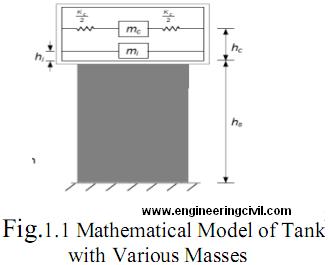
It was observed that tank liquid vibrates in two distinct pattern[1] (a) The liquid in the lower region of tank behaves like a mass that is rigidly connected to tank wall, this mass is termed as impulsive liquid mass which accelerates along with the wall and induces impulsive hydrodynamic pressure on tank wall and similarly on base (b) Liquid mass in the upper region of tank undergoes sloshing motion, this mass is termed as convective liquid mass and it exerts convective hydrodynamic pressure on tank wall and base. Thus, total liquid mass gets divided into two parts, i.e., impulsive mass and convective mass. In spring mass model of tank-liquid system, these two liquid masses are to be suitably represented. In the present work convective mass is shown by spring with a mass at a height [hc] and impulsive mass attach with the wall is shown by a mass at a height [hi] of the container.
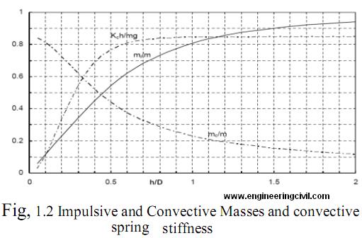
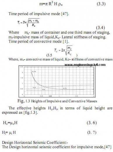
Where, S =H/D (i.e. ratio of the liquid height to diameter of the tank) [1]
Yc=mc/m (3.1)
Yi=mi/m (3.2)
Ahi= (Z/2) (I/R) (Sa /g)i — (3. 8 )
Where,
Z-zone factor=0.24, I-importance factor=1.5
Damping 5%,Ti-time period of impulsive mode.
(Sa /g)i-spectral acceleration coefficient.
Design horizontal seismic coefficient for convective mode,[47]
Ahc= (Z/2) (I/R) (Sa /g)c —- (3. 9)
Shaft is considered to have reinforcement in two curtains both horizontally and vertically.
Hence, R –Response reduction factor is taken as 1.8.
Damping 0.5% Tc-time period of convective mode.
A multiplication factor of 1.75 is used to get (Sa /g)c for 0.5% damping from that of 5% damping.
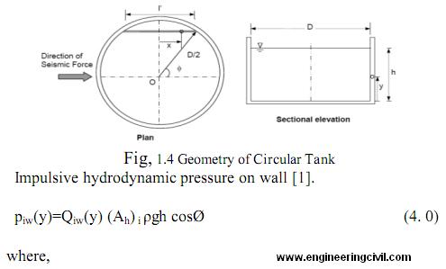
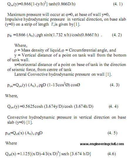
Pressure on tank wall due to inertia is given by[47].
p-(wall inertia) = (Ah)i x mass density of wall x wall thickness
B. Governing equation of motion
Structure has been model by finite element method using SAP-2000 (version 9i).The equation of motion of elevated liquid storage tanks subjected to unidirectional earthquake ground motion are expressed in the matrix form as [3]

Where {x}-displacement vector,
[m]-mass matrix
[c]-damping matrix
[k]-stiffness matrix
üg-earthquake acceleration
The convective and impulsive masses are calculated by using eq. (3.1) to (3.3) the self weight of tank and shaft is calculated automatically by the software at appropriate nodal points. The convective and impulsive masses lumped at appropriate heights by using equation (3.6) to (3.7).For non isolated tanks the bottom nodal points are given zero degrees of freedom i.e. fixed.
For isolated tanks L.R.B. types of isolation has been used, the time period of isolation is considered as 2 sec in horizontal motion. The total stiffness of isolation is equally divided among all nodal points.
C. Earthquake ground motion
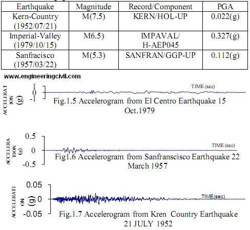
The seismic response of isolated liquid storage tanks is investigated for near fault earth quake ground motions recorded on rock. For the present study, three recorded earthquake ground motions considered are Kern Country (1952/07/21), Imperial Valley (1979/10/15) and San Francisco (1957/03/22). For the purpose of the seismic behavior of the tanks, ground motions records are put in X-component.
Records of acceleration for Kern Country (1952/07/21), Imperial Valley (1979/10/15), and Sanfracisco (1957/03/22) are as below [2].
III. DESIGN OF ISOLATORS
A practical seismic isolation system should meet the fallowing requirements.
1. Sufficient horizontal flexibility to increase the structural periods and spectrum demands accepts for very
soft soil sites.
2. Sufficient energy dissipitation capacity to limit the displacement across the isolators to a practical level.
3. Adequate rigidity to make the isolated structure not much different from a fixed base structure under general service loading.
Based on above mentioned requirements and codal procedure, as per UBC -1997, LRB isolator design
properties like damping, hardness, modulus of rigidity, and poissoins ratio for rubber are considered from UBC 1997.
Tanks under consideration here requires different size of isolators, as gravity loads acting on the column are different for different sizes of tanks, different sizes of bearings are required.
The basic equation of LRB is as follows [4].
The effective horizontal stiffness of the isolators is [4]
keff=(W/g)(2pie/TD)2=GA/t – 4.7
Where W- total weight of the tank,
G-gravitational force and taken as 9.81m/s2
TD– effective isolation period,
G- Shear modulus of the rubber,
A-cross sectional area of the bearing,
t- total thickness of rubber layer.
The design displacement DD of the isolation system along each main horizontal axis at design basis earthquake level is calculated according to the UBC97 [5]
DD=(g/4pie2)(CVDTD)/BD
—- (4.8)
CVD– Seismic coefficient CD as set forth in Table 16-R [5],
BD – Numerical coefficient related to the effective damping of the isolation system at the design displacement ßD as set forth in Table A-16-C [5],
The total design displacement including additional displacement due to accidental torsion is calculated
according to the UBC [5]
DTD=DD[1+(12ey/b2+d2)] —- (4.9)
e-actual eccentricity plus accidental eccentricity which is taken as maximum tank direction perpendicular to the direction of force under consideration, b-shortest plan dimension, d -longest plan dimension, y- distance between the center of rigidity of the isolation system[6].
The characteristics force Q is [7]
Q = (pie/2)keffßDDD (5)
ßD – damping of the isolation system
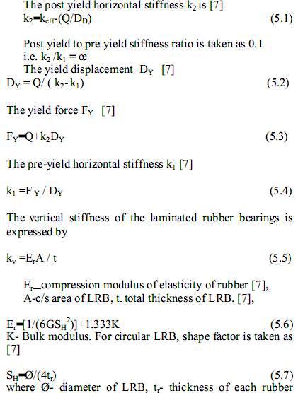
tr– thickness of each rubber layer in LRB.The details calculations of base isolators are
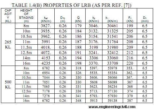
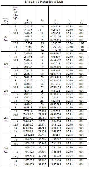
omitted here and final design parameters are listed in table no 1.5-1.6. It is important to note that analysis and design of all different types of base isolator was done using excel spread sheet
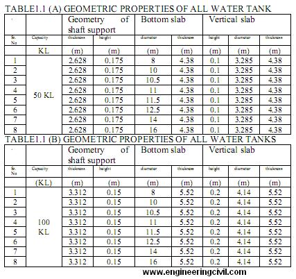
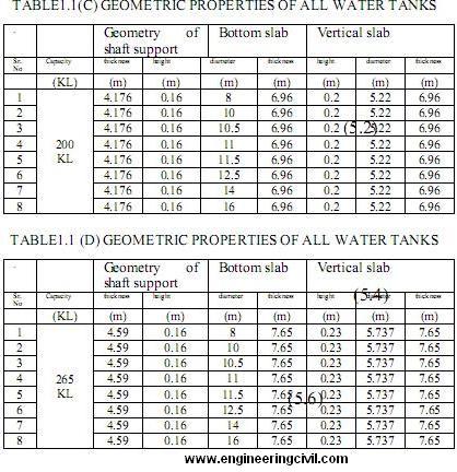
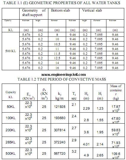
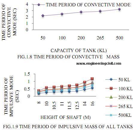
TABLE 1.4 PROPERTIES OF LRB (AS PER REF. [7])
IV. RESPONSE OF TANKS ISOLATED BY ELASTOMERIC BEARINGS SUBJECTED TO REAL EARTHQUAKES
The seismic response of isolated and fix base tanks system is investigated for the three real earthquakes excitation. The time history analysis is carried out by giving excitation in lateral direction of tank (shaft).
A. Maximum Bearing Displacement
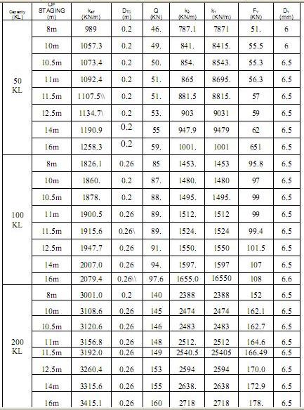
The bearing displacement increases with increase of isolation period. It becomes more flexible leading to more displacement. In the present study, time period of isolation system (target period) is TD=2 sec, damping ratio i.e. ßD=0.13and normalized yield strength i.e. Fo= Fy/W is equal to 0.05.It is found that the maximum displacement of the bearing depends upon the stiffness properties of the bearing, in present work stiffness properties of the bearings varies due to increase in the total seismic weight of the structure. Also, the vertical to horizontal stiffness ratio for 50kl, 100kl,200kl, 265kl,500kl,increase to 134,140,144,147, 148 respectively, there is a slight difference in maximum displacement in the bearing which is under the permissible limits. The maximum permissible limits for the lateral displacement of the bearing are equal to the height of the bearing. All the bearing for all the tanks did perform as desired i.e. the displacement of the bearing are well controlled by the design of the bearing.
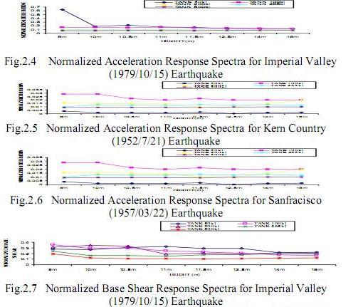
B. Maximum Acceleration Response
Response of both fixed base (non isolated tanks) and isolated tanks are investigated for three different earthquakes having different characteristics. The normalized response gives a clear idea of effectiveness of isolation for the given tanks in fig 2.4 to fig 2.6. It is observed that tanks with fixed base attracted greater ground acceleration. It is also found that all the isolated tanks performed as desired i.e. they attracted lesser ground acceleration as compared to fixed base(normalized acceleration value below 1). Isolation tanks especially the shorter height did not perform well i.e. the ground acceleration were amplified after isolation.
C. Base Shear Response
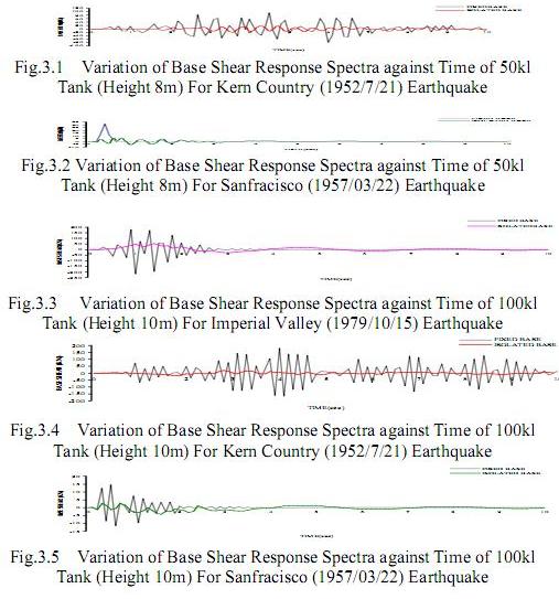
Each earthquake record considered for the time history are having properties like peak ground acceleration (PGA), frequency composition and duration varying significantly so that the inherent variability of earthquake can be accounted in the analysis. In the present study, time period of isolation system (target period) is TD=2 sec,damping ratio i.e. ßD=0.13 and normalized yield strength i.e. Fo= Fy/W is equal to 0.05, From above study it is observed that the percentage reduction of base shear under Imperial Valley (1979/10/15) earthquake for 50kl tank of height 8m, 10m, 10.5m, 11m, 11.5m, 12.5m, 14m,16m are 72,73,68,67,70,71, 78,77 which are less as compared to base shear 81,81,79,82,80,82,82,87 under Kern-Country (1952/07/21) and base shear 84,82,84,84,82,80,81,86 under Sanfracisco(1957/3/22) earthquake.
In 100kl tank the percentage reduction of base shear under Imperial Valley (1979/10/15) earthquake for 8m,10m,10.5m,11m,11.5m,12.5m,14m,16m,are,64,68,70, 74,74,78,81,83 which are less as compared to base shear,88,89,88,89,89,88,88,90,under,Kern-Country, (1952/7/21)earthquake,and,base shear, 94,87,90,87,87,87, 91, 95, under.Sanfracisco-(1957/03/7) earthquake.
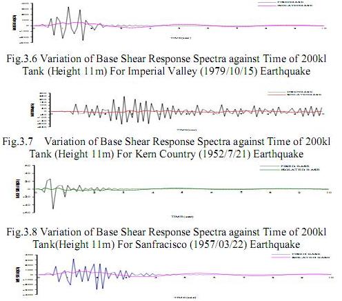
In 200kl tank the percentage reduction of base shear under Imperial Valley (1979/10/15) earthquake for
8m,10m,10.5m,11m,11.5m,12.5m,14m,16m,are 71,66,66,78,78,78,77,80 which are less as compared to base shear,89,89,89,87,90,90,92,87under,Kern-Country (1952/07/21)earthquake&base-shear,85,89,85,89
88,89,92,94 under Sanfracisco (1957/03/22) earthquake.
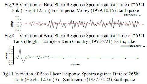
In 265kl tank the percentage reduction of base shear under Imperial Valley (1979/10/15) earthquake for
8m,10m,10.5m,11m,11.5m,12.5m,14m,16m,are,81,83, 83,85,83,83,81,75 which are less as compared to base shear 90,93,86,84,90,91,91,94 under Kern-Country (1952/07/21) earthquake and base shear 90,93,92,93,95,95,95,95 under Sanfracisco (1957/03/22)earthquake.
In 500kl tank the percentage reduction of base shear under Imperial Valley (1979/10/15) earthquake for
8m,10m,10.5m,11m,11.5m,12.5m,14m,16m,are,81,88, 89,91,89.4,89.5,88.2,87.7which are less as compared to base shear,93,94,95,95,94,94,94,95,under,Kern-Country (1952/07/21)earthquake,and,base-shear,93,96,
96,95,94,95,94,95 under Sanfracisco(1957/03/22) Earthquake.
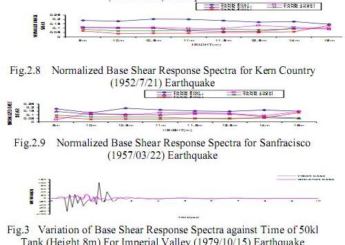
Base shear values for all the tanks are considerably reduced after isolation. It is found that all the tanks behave satisfactory under Kern-Country (1952/07/21) earthquake, and Sanfracisco (1957/03/22) earthquake as compared to Imperial Valley (1979/10/15) earthquake. It is also observed that the designed isolation system decreases the base shear value as damping of the isolation system maintains constant. In fig. 2.7 to fig. 2.9 shows the comparative graphs with height and normalized base shear for considered time history.
In fig. 3 to fig.4.1 shows the comparative graphs with time and base shear values of isolated and fixed base tanks for considered time history.
Concluding Remarks
1. Comparative performance of elevated liquid storage tanks supported on shafts by putting the base isolation system at bottom of the supporting shaft is investigated using real earthquake motions. The earthquake response of isolated tanks is compared with the non isolated (fixed base) tanks to measure the effectiveness of the isolation.
2. It is observed that the base shear of elevated liquid storage tanks supported on shaft is significantly reduced due to isolation.
3. The drift of the tank relation to base of shaft is also significantly reduced due to isolation.
4. The earthquake response of isolated short tanks is relatively more, i.e. isolation is not effective for stiffer shafts, and however in general, the effectiveness of base isolation is achieved for tall tanks.
5. Although the effectiveness of seismic isolation increases with the increase of bearing flexibility and damping these properties needs to be modified for desired response.
References
1. Jain S.K., Jaiswal O. R. IITK-GSDMA Guidelines for seismic design of liquid storage tanks
2. HTTP://PEER.BERKELEY.EDU/RESEARCH/MOTIONS
3. Shrimali M. K. And Jangid R.S. Earthquake response of isolated elevated liquid storage steel tanks, Dept.Of Civil Engg. IIT, Bombay.
4.Cenk A. and Metin A. Performance of non linear base isolation systems designed according to uniform building code, 5th international advanced technologies symposium (IATS’09) May13-15, 2009, Karabuk, Turkey.
5. International building code, UBC 1997
6. IS 3370-1967-PART I, Code of practice for concrete structure for storage of liquids Bureau of Indian standards, New Delhi.
7. Kelly, J.M., Earthquake resistant design with rubber, Springer Publishers, New York, USA (1997).
8. SAP-2000 VERSION-9 COMPUTRS AND STRUCTURES, INC, BERKELEY, CALIFORNIA
Click here to download the pdf file
We are thankful to Shri.Pravin B.Waghmare for publishing his paper on Comparative Performance Of Elevated Isolated Liquid Storage Tanks (With Shaft Staging). This paper will help other civil engineers in upcoming research on this topic.
If you have a query, you can ask a question here.