By
Shubham Sunil Malu
ABSTRACT:
As the infrastructure is developing there is need for some changes in the construction field, as one cannot rely on the same method for a long time as it can have different consequences. The main consequence is the shortage of material and manpower. Also, money matters a lot in construction department along with it the machines, equipment and technology in some region is not at a level, which we want. Hence in order to satisfy these results Bubble deck slab is one of the most effective slab techniques to replace conventional slab in terms of money and materials. Also, it requires less time to construct as compared to conventional slab.
1.0 INTRODUCTION:
Bubble Deck is a revolutionary method of virtually eliminating concrete from the middle of a floor slab not performing any structural function, thereby dramatically reducing structural dead weight. Bubble Deck is based on a new patented technique- the direct way of linking air and steel. Void formers in the middle of a flat slab eliminates 35% of a slabs self-weight removing constraints of high dead loads and short spans.
Incorporation of recycled plastic bubbles as void formers permits 50% longer spans between columns. Combination of this with a flat slab construction approach spanning in two directions – the slab is connected directly to insitu concrete columns without any beams -produces a wide range of cost and construction benefits including:-
The overall floor area is divided down into a series of planned individual elements, either 3 or2.4 meters wide dependent upon site access, which are manufactured off-site using MMC techniques. These elements comprise the top and bottom reinforcement mesh, sized to suit the specific project, joined together with vertical lattice girders with the bubble void formers trapped between the top and bottom mesh reinforcement to fix their optimum position. This is termed a ‘bubble-reinforcement’ sandwich which is then cast into bottom layer of pre-cast concrete, encasing the bottom mesh reinforcement, to provide permanent form work within part of the overall finished slab depth.
On site the individual elements are then ‘stitched’ together with loose reinforcement simply laid centrally across the joints between elements. Splice bars are inserted loose above the pre-cast concrete layer between the bubbles and purpose made mesh sheets tied across the top reinforcement mesh to join the elements together. After the site finishing concrete is poured and cured this technique provides structural continuity across the whole floor slab –to create a seamless floor slab.
BubbleDeck has proved to be highly successful in Europe since its invention ten years ago. In Denmark and Holland over 1million square meters of floors have been constructed in the last seven years using the BubbleDeck system in all types of multi-storey buildings.
OBJECTIVES
1. Used of hollow HDPE balls made up of waste plastic materials in concrete slab.
2.Reduced concrete usage – 1 kg recycled plastic replaces 100 kg of concrete.
3. Environmentally Green and Sustainable – reduced energy & carbon emissions.
4.Reduced Dead Weight– 35% removed allowing smaller foundation sizes, which result in reduced cost.
2.0 LITERATURE REVIEW: –
In the 1990’s, Jorgen Breuning invented a way to link the air space and steel within a voided biaxial concrete slab. The Bubbledeck technology uses spheres made of recycled industrial plastic to create air voids while providing strength through arch action. As a result, this allow hollow slab to act as normal monolithic two way spanning concrete slab. These bubbles can decrease the dead weight up to 35% and can increase the capacity the capacity by almost 100% with same thickness. As a result BubbleDeck slabs can be lighter, stronger and thinner than regular reinforced concrete slabs.
2.1. Millennium Tower Rotterdam Design by WZMH Architects and AGS Architects, completed in (1997-2000):
The first high rise building erected with BubbleDeck filigree-elements and the second highest building in Netherlands, 34 stories and 131 meter high. BubbleDeck was chosen, in spite of being a completely new product, because of its advantages in cost,construction time and flexibility and because of environmental issues. Beams could be excluded resulting in two more stories than planned in the beginning for the same building height. Built in 1998-2000.
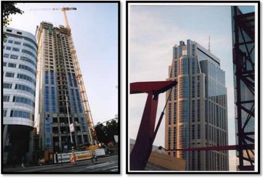
Figure 1: Millennium Tower Rotterdam
2.2. Car park(Frankfurt, Germany in 2001):
Car park built with BubbleDeck in Frankfurt Germany in 2001. BubbleDeck was chosento reduce the weight of the decks and to get wider spans.
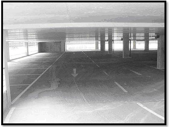
Figure 2: Car park built with Bubble Deck in Frankfurt, Germany in 2001
2.3. Media City:
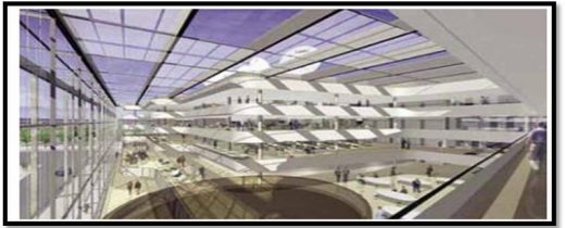
This 32,000m2 building was constructed with great transparency, revealing a huge open atrium. This atrium is the fulcrum and heart of the building. The spaces are formed in soft, organic shapes that allow light to spill onto every single workplace in the building.To achieve these wide, open, internal spaces a BubbleDeck structure of post – tensioned 450mm deep floor plates, achieving 16 meter spans between columns was selected – dramatically reducing structure dead weight and enabling long spans. The flexibility of BubbleDeck also facilitated construction of the soft flowing,organic shapes forming the floors around the central atrium.
The BubbleDeck is a revolutionary biaxial concrete floor system developed in Europe. High-density polyethylene hollow spheres replace the ineffective concrete in the center of the slab, thus decreasing the dead weight and increasing the efficiency of the floor. These biaxial slabs have many advantages over a conventional solid concrete slab: lower total cost, reduced material use, enhanced structural efficiency, decreased construction time and is a green technology.
Through tests, module and analysis from variety of institution BubbleDeck was proven to be superior to traditional solid concrete slab the reduced dead load makes the long term response more economical for the building while offsetting the slightly increased deflection of the slab however the shear and punching shear resistance of BubbleDeck floor is significantly less than a solid deck since resistance is directly related to the depth of concrete design reduction factor have been suggested to compensate for these differences in strength this system is certified in the Netherlands, the United kingdom, Denmark and Germany.
Reinforced concrete slabs are components commonly used in floors, ceiling, garages and outdoor wearing surfaces
The BubbleDeck system is based upon the patented integration technique- the direct way of linking air and steel.The BubbleDeck is a two-way hollow deck in which plastic balls serves the purpose of eliminating concrete that has no carrying effect.By adapting the geometry of the ball and the mesh width, an optimized concrete construction is obtained, with simultaneous maximum utility of both moment and shear zones.The construction literally creates itself as a result of the geometry of the two well-known components: Welded reinforcing mesh and hollow plastic balls. When the top and bottom reinforcing meshes are connected in the usual way, a geometrical and statically stable BubbleDeck unit evolves.
The reinforcing mesh catches, distributes and locks the balls in exact position, while the balls shape the air volume, control the level of the reinforcing meshes, and at the same time stabilize the spatial lattice. When the steel lattice unit is concreted, a “monolithic” two-way hollow slab is obtained.
3.0 FLOW CHARTS: –
3.1.PHASE I: –
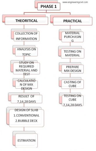
4. MATERIALS AND TESTS
4.1. MATERIALS: –
4.1.1. POLYETHYLENE BUBBLES
Polyethylene is derived from either modifying natural gas (a methane, ethane, propane mix) or from the catalytic cracking of crude oil into gasoline. In a highly purified form, it is piped directly from the refinery to a separate polymerization plant. Here, under the right conditions of temperature, pressure and catalysis, the double bond of the ethylene monomer opens up and many monomers link up to form long chains. In commercial polyethylene, the number of monomer repeat units ranges from 1000 to 10 000 (molecular weight ranges from 28 000 to 280 000). The bubbles are made of polyethylene they do not react chemically with the concrete and/or the reinforcement steel.The bubbles are non-porous and possess enough strength and stiffness to carry applied loads safely in the phases before and during the pouring of the site concrete.
4.1.2. CEMENT
Ordinary Portland cement can be used it should confirm all standards as specified. Cement remained stored for more than 60 days from the date of receipt from factory shall be rejected.
4.1.3. COARSE AGGREGATE:
It shall be hard broken stone of granite or similar stone free from dust and other organic and non-organic matter. We use 20 mm & mix aggregate.
4.1.4. FINE AGGREGATE
Shall be coarse sand consisting of hard sharp and angular grains and shall pass through screen of 4.75 mm square mesh. Fine aggregate should be free from dust, silt and other organic and non-organic matter.
4.1.5. WATER
The water used should be fresh and free from alkaline and acid matter and it should be potable. Generally drinkable water should be used.
| SR. NO. | DESCRIPTION | RESULT |
| 1. | Initial And Final setting time | IST=180min FST=520min |
| 2. | Standard consistency of cement | 33.25% |
| 3. | Soundness of cement | 2mm |
| 4. | Fineness modulus and grading of fine aggregate and coarse aggregate | fine-2.6 coarse-3.2 |
| 5. | Moisture content of fine aggregate | 0.403% |
| 6. | Specific gravity of fine aggregate | 2.65 |
| 7. | Determination of moisture content of coarse aggregate | 2.378% |
| 8. | Specific gravity and water absorption test of coarse aggregates | sp.g-2.80 water absorbtion-0.5 |
| 9. | Flakiness and Elongation of coarse aggregate | flakiness-17.83% elongation-16.47% |
Table 1: Result Summary
5.0 MIX DESIGN (M20)
5.1. MIX DESIGN CALCULATION:
Data
Grade of concrete = M 20
Type of cement = OPC 53 grade
Maximum size of aggregate = 40 mm
Minimum cement content = 300 kg/m3
Maximum cement content = 450 kg/m3
Maximum water cement ratio = 0.55
Degree of workability = 75 mm
Exposure condition = mild
Specific gravity of cement =3.15
Specific gravity of aggregate-
a) Coarse aggregate = 2.80
b) Fine aggregate = 2.65
Water absorption –
a) Coarse aggregate – 4.02 %
b) Fine aggregate – 1.27 %
Free moisture –
a) Coarse aggregate – 2.378 %
b) Fine aggregate – 0.403 %
Sieve analysis –
a) Coarse aggregate – 3.2
b) Fine aggregate – 2.6
Target mean strength-
fck = fck + 1.65 × standard deviation
= fck + 1.65 × 4
= 26.6 N/mm2
Selection of W/C ratio-
Maximum W/C ratio = 0.55
Water / cement ratio is taken from the experience of the mix designer based on this experience of similar work elsewhere Adopt W/C ratio = 0.48
Selection of water content-
Degree of workability = 75 mm
Maximum water content = 186 kg
Estimated water content for 75 mm slump = 186 × (3/100) + (186)
= 191.58 liters
Calculation of cement content
W/C ratio = 0.48
Water used = 191.58 liter
Cement = 191.58 /0.48
= 399 kg/m3 > 300kg/m3 …… ok
Calculationof coarse and fine aggregate content –
Volume of coarse aggregate for 40 mm maximum size aggregate and fine aggregate 0.05 Falling in the zone-I and w/c ratio 0.48 is found out to be 0.64.
When w/c ratio is 0.5 and fine aggregate zone-I in that case volume of coarse aggregate is 0.60 %.
For every decrease of w/c by 0.05, the coarse aggregate volume may be increase by 1 % to reduce the sand content.
Coarse aggregate for the w/c ratio of 0.48
Volume of coarse aggregate = 0.64
Volume of fine aggregate = 1- 0.64
= 0.36
Mix calculation-
Volume of concrete = 1m3
Absolute volume of cement = 399/3.15 x 1/1000
= 0.126 kg/m3
Volume of water = 191.58/1000
= 0.1915 m3
Total volume of all in aggregate = 1- (0.126 + 0.1915)
= 0.682 m3
Wt. of coarse aggregate = 0.682 x volume of CA x specific gravity of CA x 1000
= 0.682 x 0.64 x 2.80 x 1000
= 1222.14 kg/m3
Weight of fine aggregate = 0.682 x 0.36 x 2.65 x 1000
= 650.62 kg/m3
Mix proportioning for trial
Cement =399 kg/m3
Water = 191.58 kg/m3
Fine aggregate = 650.62 kg/m3
Coarse aggregate = 1222.14 kg/m3
Weight density =399 + 191.58 + 650.62 + 1222.14
= 2463.34 kg/m3
W/c ratio = 0.48
Field correction
Fine aggregate quantity = 650.62kg/m3
Absorption = 1.27 %
Quantity of absorption = 1.27/100 x 650.62
= 8.26 kg/m3
Surface moisture= 0.403 %
Quantity of surface moisture = 0.403/100 x 650.62
= 2.62 kg/m3
Weight of fine aggregate in field condition = 650.62 + 8.26 – 2.62
= 656.26 kg/m3
Coarse aggregate quantity = 1222.14 kg/m3
Quantity of absorption = 4.02/100 x 1222.14
= 49.13 kg/m3
Quantity of surface moisture = 2.378/100 x 1222.14
= 29.06 kg/m3
Weight of coarse aggregate in field condition
= 1222.14 + 49.13 – 29.06
= 1242.21 kg/m3
| Sr. no. | Content | Quantity
(kg/m3) |
| 1 | Cement | 399 |
| 2 | Water | 191.58 |
| 3 | Fine aggregate | 656.26 |
| 4 | Coarse aggregate | 1242.21 |
| 5 | Weight density | 2489.05 |
Table 2: Mix Design Results
Cement: fine aggregate: coarse aggregate
399:656.26: 1242.21
1: 1.64: 3.11
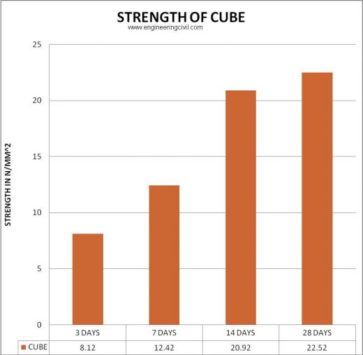
5.2. CUBE CASTING RESULTS: –
| CUBE 1 (N/mm²) | CUBE 2(N/mm²) | CUBE 3(N/mm²) | |
| 3 DAYS | 7.82 | 8.12 | 9.42 |
| 7 DAYS | 14.22 | 12.42 | 12.92 |
| 14 DAYS | 18.11 | 20.92 | 23.76 |
| 28 DAYS | 25.13 | 22.52 | 24.11 |
Table 3: Cube Casting Results
6.0 DESIGN OF SLAB: –
6.1. CONVENTIONAL SLAB: –
Design of 3×3 conventional slab
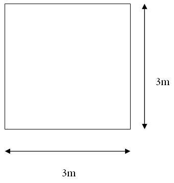
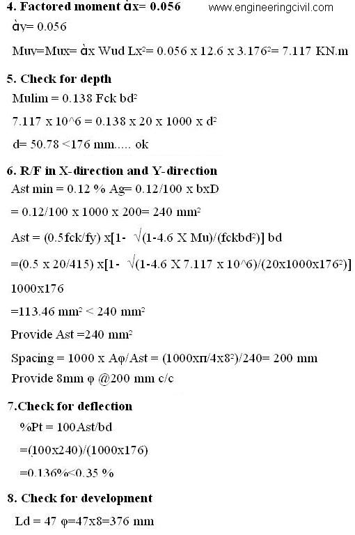
Ly/ Lx= 3/3=1 <2......two way slab 1. Trial depth
d = Lx/ (20 MF)= 3230/(20 x 1.4) …. assume 0.35% Pt
d = 115.35mm
D = 200 mm
d= D – cover – ?/2
= 200-20-8/2
=176 mm
D= 200 mm
D=176 mm
2. Effective span
Leff= Lx + d= 3000+176=3176
3. Load calculation
Self weight = 25 x d= 25 x 176= 4.4 KN/m
Live load = 3 KN/m
Floor finish = 1 KN/m
Total load = 8.4 KN/m
Wud = factored load = 8.4 x 1.5= 12.6 KN/m
6.2. DESIGN OF BUBBLE DECK SLAB:-
Design of 3×3 bubble deck slab

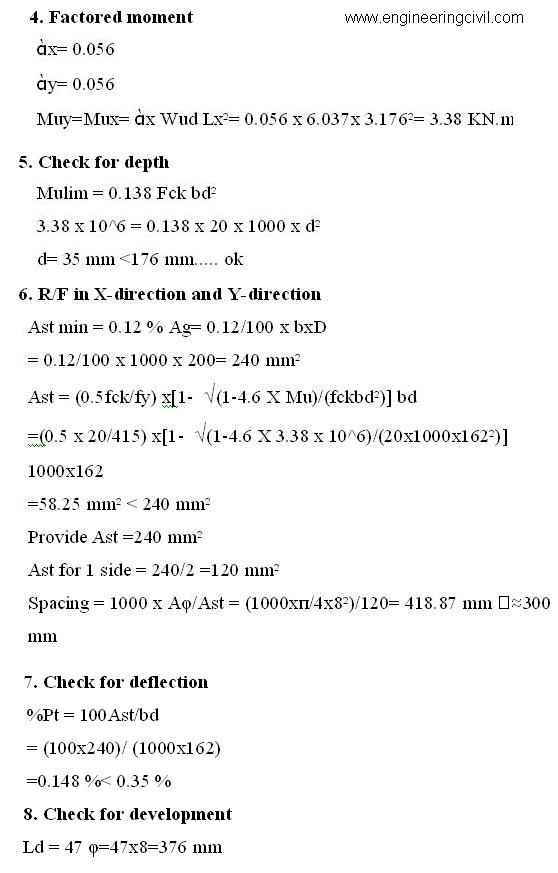
Ly/ Lx= 3/3=1 <2......two way slab
1. Trial depth
D = 200 mm
d= D – cover - ?/2
= 200-34-8/2
=162 mm
D= 200 mm
d=162 mm
2. Effective span
Leff= Lx + d= 3000+176=3176
3. Load calculation
Self-weight = 25 x d= 25 x 162= 4.05 KN/m
Live load = 3 KN/m
Floor finish = 1 KN/m
Total load = 8.05 KN/m
Reduced 50% = 50/100×8.05=4.025Kn/m
Wud = factored load = 4.025 x 1.5= 6.037 KN/m
7.0 ESTIMATION OF SLABS: –
7.1. CONVENTIONAL SLAB:-
ESTIMATION OF CONVETIONAL SLAB
1.STEEL
Length of bent up bar
= L -2xend cover + 2hooks+ one depth
=3230-2x16x8+160
=3.606 m
Weight of bar per m= φ/162 = 8²/162=0.395 kg
Number of bars @ x-direction=15 NOS.
Number of bars @ Y-direction=15 NOS.
Total weight of steel in 3×3 slab= weight of bars in x-direction + weight of bars in y-direction
=(0.395x15x3.606) + (0.95x15x3.606)=21.36+21.36=42.74 kg
Cost of steel (TATA STEEL)
cost per kg = Rs. 44/-
=42.14 x 44
= Rs. 1879.92/-
2.Mix proportion M20 (1:1.78:2.15)
Volume of concrete =3x3x0.2
=1.8 m3
3.Cement
Volume of cement = [(1.52×1.8)/(1+1.78+2.15)]x1
=0.554 m3
Number of bags =0.554×30=16 NOS.
Cost of cement =300×16=Rs.4800/-
4. Sand
Volume of sand= 0.554×1.78=0.986 m3
i.e. 0.986/2.83=0.348 brass
Cost of sand
(0.5 brass=Rs.3200/-)
For 0.348 brass= Rs.2227.2/-
5. Aggregate
Volume of aggregate = 0.554×2.15=1.191 m3
i.e. 1.191/2.83=0.42 brass
Cost of aggregate
(1 brass=Rs.2300/-)
For 0.42 brass = Rs.966/-
6. Other cost
Head mistry 1 = Rs.1000/-
Mistry 1 = 750/-
Mixer operator 1= 400/-
Vibrator operator 1= 400/-
Labour 6= 1800/-
Water charges =1000/-
Tools and plants =1300/-
Total=6650+850(extra)
=7000/-
7.summary
Steel =1880/-
Cement =4800/-
Sand =2228/-
Aggregate =966/-
Other = 7000/-
total =16877+300=17177/-
Contractor profit=10%x17177=1717.7
Total cost for 3x3x0.2 m slab is 17177+1717.7=18894 =approx 19000/-
7.2.BUBBLE DECK SLAB: –
ESTIMATION OF BUBBLE DECK SLAB
1.STEEL
Length of bent up bar
= L -2xend cover + 2hooks+ one depth
=3230-2x16x8+160
=3.606 m
Weight of bar per m= φ/162 = 8²/162=0.395 kg
Bottom: –
Number of bars @ x-direction=10 NOS.
Number of bars @ Y-direction=10 NOS.
Top:-
Number of bars @ x-direction=10 NOS.
Number of bars @ Y-direction=10 NOS.
Wt. Of bar per meter = 0.395 kg.
Top= 3.395x10x3.606 = 14.243 kg……….x-direction
= 3.395x10x3.606=14.243 kg………..y-direction
Bottom=3.395x10x3.606 = 14.243………x-direction
= 3.395x10x3.606=14.243 kg………..y-direction
Total steel=56.974 kg
Cost per kg Rs 44 /-
= 56.974×44
=Rs 2506.89/-
2.Mix proportion M20 (1:1.78:2.15)
Volume of concrete =3x3x0.2 –(5.235×10-4 x841)
=1.8-0.440
=1.359 m3
3.Cement
Volume of cement = [(1.52×1.359)/(1+1.78+2.15)]x1
=0.419 m3
Number of bags =0.419×30=12.57 = approx 13NOS.
Cost of cement =300×13=Rs.3900/-
4. Sand
Volume of sand= 0.419×1.78=0.265 m3
i.e. 0.265/2.83=0.093 brass
Cost of sand
(0.5 brass=Rs.3200/-)
For 0.0.093 brass= Rs.595/-
5. Aggregate
Volume of aggregate = 0.419×2.15=0.90 m3
i.e. 0.90/2.83=0.318 brass
Cost of aggregate
(1 brass=Rs.2300/-)
Foe 0.318 brass = Rs.731/-
6. Other cost
Mistry 1 = 750/-
Mixer operator 1= 400/-
Vibrator operator 1= 400/-
Labour 4= 1200/-
Water charges =1000/-
Tools and plants =1300/-
Crane charges =500/-
Total=5550/-
=5550/-
7.Summary
Steel =2506/-
Cement =3900/-
Sand =595/-
Aggregate =731/-
Other = 5550/-
HDPE balls=1800/-(900 bals)…………RS.2/- each
total =13281 + 300+1800 =15381 = approx 15400/-
Contractor profit=10%x15400=1540/-
Total cost for 3x3x0.2 m slab is 15400+1540=16940/-
7.3. COST COMPARISON:-
(TABLE NO. 4)
| Sr. no | Description | Cost in Rs. | |
| Conventional slab | Bubble Deck slab | ||
| 1. | Steel | 1880/- | 2506/- |
| 2. | cement | 4800/- | 3900/- |
| 3. | sand | 2228/- | 595/- |
| 4. | Aggregate | 966/- | 731/- |
| 5. | HDPE Balls | – | 1800/- |
| 6. | Other | 7000 | 5550/- |
| Total | 17177/- | 15400/- | |
| Contractor profit 10% | 1717.7/- | 1540/- | |
| Grand Total | 19000/- | 16940/- | |
| Net Profit | (19000-16940)/19000×100=10.84% | ||
Table 4: Cost comparison between Conventional slab and Bubble Deck slab
8.0 BIBLIOGRAPHY:-
1. IS: 10262-2009 for mix design.
2. IS: 456-2000
3. IS: 2386 (PART I, III, IV)-1963 for testing of aggregate.
4. IS: 4031 (PART IV, V) – 1988 for test on cement.
5. IS: 269-1976-for test on cement.
6. Churakov 1:- (ArtemyGeorgievichChurakov, B.Sc) Construction of Unique Buildings and Structures ISSN 2304-6295. 6 (21). 2014. 70-88
7. Technical University of Cluj-Napoca, Faculty of Civil Engineering. 15 C Daicoviciu Str., 400020, Cluj-Napoca, Romania
8. EurIng R A Beeton BSc CEng MICE, BubbleDeck’s Design Engineer, April 2006
9. Department of Civil Engineering, Ho Chi Minh City University of Technology, Vietnam National
10. German Test Certificate Number P-SAC 02/IV-065 according to DIN 4102-2.
11. Mr. Paul Harding, M.D. , Bubble deck international, United Kingdom.
9.0 CONCLUSION: –
As per our test we conclude that all results satisfy the requirement of IS 10262-2009.Our Mix design satisfies the IS requirement. Hence we can proceed further for casting slabs.From the results, we can conclude that the cost of Bubble Deck is less as compared to conventional slabs.Hence, it is suitable for construction in terms of cost, quality and maintenance.
10.0. REFERENCES: –
1. Bubbledeck structure solutions United Kingdom.
2. Prof. M. P. Nielson- The technical university of Denmark.
3. The Eindhoven University of Technology- the Netherlands.
4. Technical university of Darmstadt- Germany.
5. German Test Certificate Number P-SAC 02/IV-065 according to DIN 4102-2.
6. Mr. Paul Harding, M.D., Bubbledeck international, United Kingdom.
7. www.BubbleDeck-UK.com
8. www.BubbleDeck.com
9. www.bbdna.com
If you have a query, you can ask a question here.


i am civil engineer who is fan of you
How you have decided the Size of the balls for the Bubble deck please Explain