Introduction:
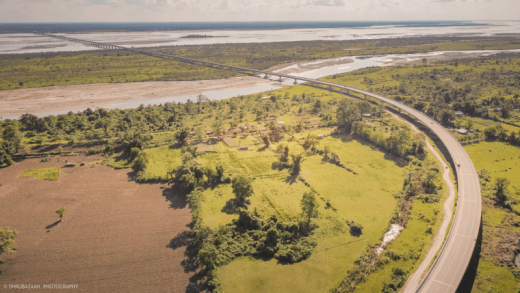
Dhola-Sadiya Bridge or The Bhupen Hazarika Setu is over the river Lohit, a tributary of the river Brahmaputra. It is a beam bridge in India which connects the north eastern state Assam and Arunachal Pradesh. The bridge spans from the village Dhola (Tinsukia District) in the south to Sadiya to the north. Total length of the bridge is 9.15 km and width is 12.9m.

Fig 1: The Dhola-Sadiya Bridge
Courtesy: Dhrubazaanphotography @ wikipedia.org
Construction of the bridge:
The construction of the bridge was started from November 2011 and ended on 10th March 2017. It was constructed by the Ministry of Road Transport along with Navayuga Engineering Engineering Company Ltd under the public-private-partnership agreement.Total cost of the bridge was Rs2,056crore. Besides facilitating numerous hydro power projects coming up in the state, it is the most sought after route for various power project developers. The bridge has a three-lane carriageway and also caters to the strategic requirements of the country in border areas of Arunachal Pradesh.
The location of the Bridge falls under seismic zone V, which has the maximum intensity. Though there is no coastal area near the bridge location, the wind velocities are high. The design wind speed is given as 50m/s. Along with these, the water current velocity is high. The design of such structures in this area is somewhat difficult. But the subsoil consists of fine sand which is likely to be favourable.
The structure:
The bridge is divided into two parts for the sake of design: proper river portion and flood plain portion. The river portion is deeper and there is perennial flow of water. Piles in this portion are subjected to higher forces than those in flood plains. The bridge piers are founded on piles. Each pile is supported by four supporting piles. The floodplains in that area get dried during the non-monsoon period. The current forces on the piles are high and the scour of the bed in the river portion is deeper. In addition to these, horizontal forces from seismic activity, braking of vehicles and temperature variations will induce heavier bending moments on the piles. The basic span of the superstructure is 50 meter. There are a total 183 spans having 101 over the flood plains and 82 in the river portion. High earthen embankments approaching from both sides are considered as important components for the bridge. There are some other minor bridges also located in the approach embankments. The total width of the bridge is 13.2m which can be divided into a motor carriageway of 10.5m with a foot path of 0.9 m on either side of the carriage way. There are two crash barriers on either side for safety of vehicles.
Foundation of the Bridge:
For the foundation of the bridge, bored cast-in-situ piles have been employed. The piles in the river portion have higher diameter (1700mm) than that of in the flood plains (1500 mm). Piles are used to resist the vertical and horizontal loads coming on them. Piles transfer the vertical loads on the subsoil by friction between soil and pile and resistance by the soil. The length of each pile is 40m. The total number of piles in the river portion is 324 and in the floodplain portion is 412. Piles are connected by a pile cap at the top.
The measurement of pile caps in the river portion is 7.3m x 7.3m x2.55m and that of flood plains is 6.4m x6.4m x2.25m. The bottom of each pile is kept sufficiently above the low water level to facilitate the casting of caps. In the river portion, the vertical load on the pile is 520 tonnes. Piles were tested for higher loads of 1300 tonnes to satisfy their performance. The characteristic strength of concrete used is 40MPa, i.e M40 concrete. Piers are located on the centre of the top of the pile cap. Piers are used for transferring load from the superstructure.

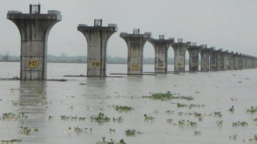
Fig 2: Pier construction of the bridge
Courtesy: Nbm &Cw
Superstructure:
The superstructure of the bridge is made of segmental box type structure. Each box is externally post tensioned with high tensile strands. The method used for the superstructure is pre-cast method which reduces the time gap between the construction periods. It can be done in a shorter period as the construction process reaches the bearing level. Since full length of box cannot be transported to the casting yard, so boxes are cut into segments which are called segmental construction. The weight of each segment is kept minimum for handling purpose. Since the segments are externally post tensioned, this will avoid the cables passing through the inside of the web of box. This will also reduce its thickness and weight of segments. The characteristic strength of post tensioned concrete is 50 MPa and that of high tensile steel strands is 1860MPa. There are 15 number of segments present for a span of 50 m. The superstructure of the bridge rests on elastomeric bearings. The bearings will accommodate the rotation and translation movement of the girder. The design procedures follow IRC 112 and 6.

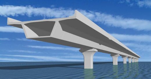
Fig 3: Animation of segmental construction of the bridge
Courtesy: Nbm &Cw
The height of the embankment of the bridge is 10m. As the height is more, so it is a complex based abutment. Abutment is the interface of the bridge with approach embankment. Soil is retained on one side of the abutment. The height of retention of the bridge is 6.5m, so a cantilever retaining wall is designed.
The location of the bridge falls in a high seismic zone. The seismic force acts through the center of gravity of the mass. The mass of this heavy structure centered at the top. The horizontal force acts at this level induce heavy bending moment in the pier and that also goes to the piles. So piles and piers are designed for seismic force. This force has to be successfully transferred from the superstructure to the foundation and ultimately to the ground. There should be effective load transfer at every connection of the bridge. Since the superstructure is simply rested on the bearings, it should be prevented from moving sideways or falling out of the pier. Seismic arresters are used for this purpose. These work in resisting the seismic loads and transferring them to the piers. For transverse forces vertical reinforcements are used and for longitudinal forces stress bars are used.
The project was a huge one. Total 736 piles were installed. It required massive scale infrastructure. During the construction, three batching plants and 12 transit mixers were operated simultaneously. Three hydraulic rotary piling rigs were used. For lifting and placing reinforcement cages and liners, cranes were used. Shuttering for the pile cap was massive as there were 182 piers. The piers had a special shape and moulds for these were a colossal requirement.
Conclusion:
The bridge links Dhola in Assam to Sadiya in Arunachal Pradesh. Earlier at this location, the only means to cross the Brahmaputra was by ferry in the daytime, it was almost not possible during floods. Now this bridge gives connectivity between upper Assam and eastern part of Arunachal Pradeshand also reduces the travel time from 6 hours to one hour. It is expected that the bridge will enhance India’s defence capabilities in the northeastern region as it requires less time to journey to the India-China border.
If you have a query, you can ask a question here.


