

By
Preetpal Kaur Ragbir Singh, Assoc. Prof. Dr, Nasir Shafiq
University Technology Petronas, Bandar Seri Iskandar.31750,Tronoh, Perak, Malaysia
Abstract
Design, construction and maintenance requirements of tall buildings and industrial complexes are very different from those applicable for normal building design and construction. For example, for conveying the services and other facilities such as water supply, electricity, air-conditioning and sewerage discharge; a complex network of system routing is provided, which usually align vertically and horizontally and spread throughout the floor area. This complex network is often obstructed by the structural components such as beams, columns and floors and requires to penetrate through such obstruction, which is called the structural penetrations. The size, location and configuration of structural penetration are derived from the type of services, magnitude and speed of facility to be provided. The most prevalent location, size and configuration of structural penetration are always an issue between structural engineers and service or facilities design engineers. This research focuses on the effects of static loading on reinforced concrete beams with openings. This research also studies the prospect of strengthening the beams by using external bonded CFRP in different combinations or arrangement to regain bending capacity that was lost due to the openings. The openings are circular, rectangular, square and elliptical shaped.
Keywords
CFRP Sheets, Large Opening, Static, RC Beam.
I. INTRODUCTION
esign, construction and maintenance requirements of tall buildings and industrial complexes are very different
from those applicable for normal building design and construction. For example, for conveying the services and other facilities such as water supply, electricity, air-conditioning and sewerage discharge; a complex network of system routing is provided, which usually align vertically and horizontally and spread throughout the floor area. This complex network is often obstructed by the structural components such as beams, columns and floors and requires to penetrate through such obstruction, which is called the structural penetrations. The size, location and configuration of structural penetration are derived from the type of services, magnitude and speed of facility to be provided. The most prevalent location, size and configuration of structural penetration are always an issue between structural engineers and service or facilities design engineers. Penetration means the loss of concrete area, which results in the reduction of resistance in the term of strength and axial stiffness. The way penetration area is configured, the flexural or shear stiffness
and deflection resistance of the beam is also affected.
In tension and compression mode, concrete and steel have different behaviors. Concrete in compression is affected by the confinement. This is due to the stirrups and the buckling of the steel bars in compression mode. The steel reinforced bars must carry the tensile loads even though there are cracks in concrete to achieve its full load. Adequate bond between concrete and reinforcing steel is required to transfer tensile forces from concrete to the reinforcing steel. Concrete and steel may lead to longitudinal cracking (creating several durability problems), excessive deformation and a decrease in load carrying capacity when concrete and steel bond is weaken.
The carbon fibre reinforced polymer (CFRP) is one of the reinforced materials that are widely used for repairing all kind of RC structures. The CFRP is used as external reinforce to the concrete members. The CFRP is different from other reinforced material because it is used to reinforce the concrete members internally. The material used in upgrading and strengthening structural capacity is CFRP. CFRP strips are lighter, non-corrosive, and less intensive than the application of the steel plate or exterior post-tensioning. Structural elements can increase its strength by pasting CFRP externally. The lightweight of CFRP strips can provide ten times the tensile strength of steel. The capability of the CFRP to carry loads in tension can be a way to strengthen against flexural, shear or compression, depending on how the CFRP strips are oriented to the longitudinal reinforcing steel. CFRP bonding leads to a slower critical diagonal cracks and enhances the load-carrying capacity of the beam. It will enhance the load carrying capacity up to a level that is sufficient to meet most of the practical upgrading requirements. To overcome such problems pasting CFRP can be one of the solution rather than reconstruction of the whole structure. Pasting CFRP is less costly and more effective.
To ensure safety and adequate warning before failure happens; structures should be designed to fail in ductile mode. It is well known that the failure of RC beams for fatigue and static loading is caused by lack of shear strength and ductility. The shear strength should be high enough to avoid the brittle shear failure that may occur before flexural failure. Under fatigue loading, opening and closing of diagonal cracks in two opposite directions tend to reduce the shear strength and concrete stiffness which results in decreasing the effectiveness of aggregate bond. Openings should not be placed at the critical bending and shear zone which will cause severe structural failures. The two main objectives of this study are to determine the effects of openings on RC beams under static loading in the terms of capacity loss and to determine the effectiveness of using carbon fiber reinforced polymers (CFRP) which ensures the return of the lost capacity under static loading.
II. EXPERIMENTAL DETAILS
This research scope is divided into experimental or testing method and data analyzing. Experimental method was carried out to test the effects of static loading on RC beams with openings in the critical tensile zone. Experiments were further carried out to determine the effectiveness of using carbon fiber reinforced polymers (CFRP) which ensures the return of the lost capacity under static loading. The experiment was carried out for reinforced concrete beams with circular, rectangular, elliptical and square openings. Nine beams of concrete strength fcu=+/- 35Mpa were cast and were subjected to static loading to obtain the failure load. The research only focuses on 4 types of different openings. As these openings are mostly constructed openings. Circular openings accommodate service pipes, such as for plumbing and electrical supply. Rectangular openings accommodate rectangular air conditioning ducts. The beams have 2T12 rebar as the bottom bars and 2T10 bars at the top of the beam. These bars act as the main bars in the beams. The beams also have stirrups of R6 bars with spacing of 300mm center to center. The beams were cast using the ready mix concrete with the concrete strength of 35Mpa. The concrete cover used was 20mm top and bottom. The beams were tested after 28 days using the self straining loading frame machine. The solid beam is tested first. Then the beams with the circular and square opening were tested continued rectangular and elliptical beams. The CFRP is pasted based on the crack pattern that is obtained from the tested beams.
III. RESULTS AND DISCUSSION
In this part experimental results of all beams subjected to static loading are presented and discussed. One solid beam (as reference beam), one beam with circular opening, one beam with square opening, one beam with rectangular opening and one beam with elliptical opening were tested under static loading. All these beams were not pasted with any CFRP sheet. The static load was applied at the rate of 0.15kN. Static load was applied until the beam fails. The static load was applied as two symmetrical point load. Fig. 2 shows the results plotted in graph and Table 2 shows the summary of static loading.
Fig. 2 shows the experimental load-deflection graph for all the beams tested under static loading without any strengthening method. The initial linear part of the graph has a very steep slope for all the curves, which corresponds to the uncracked condition of these beams. In this region, the deflection is proportional to the applied load and the entire concrete section is considered effective in resisting the loads. As can be observed from Fig. 2, the behavior of all type of beams is similar before cracking when the beams are stiff. The end point of this linear part for all the curves is an indication of the starting point of cracking in the beam. The next segment that immediately follows this linear part for all the curves provide information about the bond quality and tension stiffening effects due to crack spacing. The slope of this part is smaller than the slope of the initial linear segment for all the curves. This shows that the rate of deflection per unit load is higher after the beam has cracked. This is an indication of the reduction in the stiffness of the cracked beams. The last part of the curves shows the possible failure mechanism of the structure. As shown in Fig. 2 all the beams showed a very ductile behavior and all beams failed at nearly the same load after undergoing considerable deformation with very small increase in the load once steel yielded.
Table 2 shows the summary of ultimate load and deflection of beams tested under static loading. The ultimate load here is referred to the maximum load carried by the beam. All the beams with opening are compared with solid beam on the ultimate load. Beam with elliptical and rectangular opening gain strength compared to solid beam. Beam with circular and square opening lost strength compared to solid beam. This is due to the additional bars along the elliptical and rectangular opening beam. Therefore, bars along the opening area can increase the strength and control the crack width under service load. Deflection at the failure point of solid beam is also high if compared to beam with circular, rectangular and elliptical whereas beam with square opening has higher deflection at failure point if compared to solid beam. Beam with circular opening does not have any sharp edges but beam with square opening have sharp edges. Deflection increases if many cracks appear in the beam. Sharp edges will enhance more cracks and eventually higher deflection rate at failure point. Beam with elliptical and rectangular opening has lower deflection at failure point because these beams have additional bars along the opening area. Therefore, bars along the opening area can decrease the deflection at failure point.
The yield strength or yield point of a material is defined as the stress at which a material begins to deform plastically. Prior to the yield point the material will deform elastically
TABLE I SPECIMEN DETAILS
| Beam
No |
CFRP
Strengthening |
Shape of
Opening |
Spam of Beam
(mm) |
Design
Strength (MPa) |
Number of
Openings |
Location of Opening
from support |
Type of
Loading |
| 1 | No | None | 2300 | +/- 35 | 0 | No | Static |
| 2 | No | Square (240 X240 mm) | 2300 | +/- 35 | 2 | 850mm | Static |
| 3 | Yes | Square (240 X240 mm) | 2300 | +/- 35 | 2 | 850mm | Static |
| 4 | No | Circular (?270 mm) | 2300 | +/- 35 | 2 | 850mm | Static |
| 5 | Yes | Circular (?270 mm) | 2300 | +/- 35 | 2 | 850mm | Static |
| 6 | No | Cylinder (?125 mm, h=500mm, d=250mm) | 2300 | +/- 35 | 1 | 875mm | Static |
| 7 | No | Cylinder (?125 mm, h=500mm, d=250mm) | 2300 | +/- 35 | 1 | 875mm | Static |
| 8 | No | Rectangular (700mm x 250mm ) | 2300 | +/- 35 | 1 | 900mm | Static |
| 9 | No | Rectangular (700mm x 250mm ) | 2300 | +/- 35 | 1 | 900mm | Static |
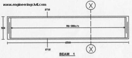
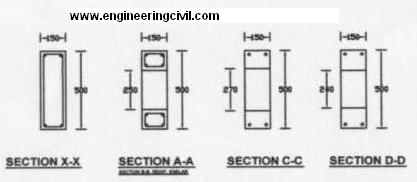
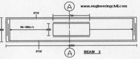
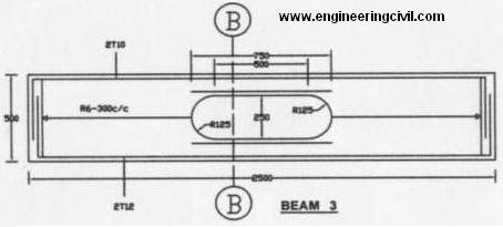
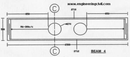
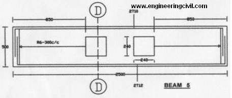
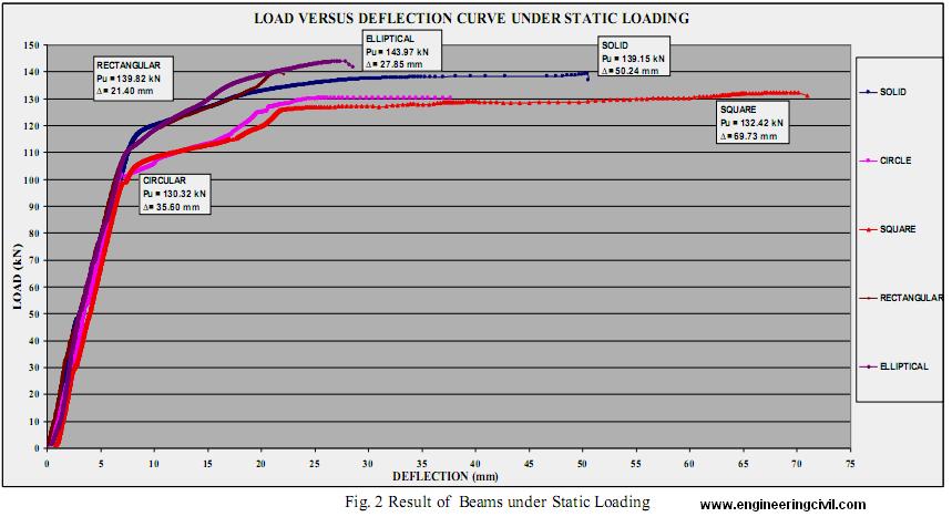
TABLE 2 SUMMARY OF STATIC LOADING
| Solid Beam
(Reference Beam) |
Beam with
Circular Opening |
Beam with
Square Opening |
Beam with
Elliptical Opening |
Beam with
Rectangular Opening |
|
| Ultimate load under static condition (kN | 139.15 kN | 130.32 kN | 132.42 kN | 143.97 kN | 139.82 kN |
| % lost or gain in strength due to opening | Nil | -6.30% | -4.80% | +3.50% | +0.50% |
| Deflection at failure point (mm) | 50.24 mm | 35.60 mm | 69.73 mm | 27.85 mm | 21.40 mm |
| Deflection at yield strength (mm) | 8.81 mm | 7.36 mm | 7.80 mm | 7.41 mm | 7.23 mm |
| Load at yield strength (kN) | 117.62 kN | 100.10 kN | 106.37 kN | 110.18 kN | 109.35 kN |
| Deflection at 35% of the ultimate load (mm) | 2.41 mm | 3.26 mm | 3.68 mm | 3.08 mm | 2.84 mm |
| Opening proportion to the beam depth % | Nil | 54%Large Opening | 48%Large Opening | 50%Large Opening | 50%Large Opening |
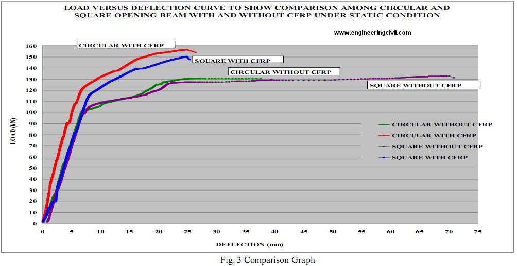
TABLE 3
SUMMARY OF STATIC LOADING WITH AND WITHOUT CFRP SHEETS
| Solid Beam With Additional Bars | Beam with Circular Opening
With CFRP Sheets |
Beam with Square Opening With
CFRP Sheets |
|
| Ultimate load under static condition (kN | 149.40 kN | 156.21 kN | 150.06 kN |
| % gain in strength due to strengthening
method |
7.40% | 19.90% | 13.30% |
| Deflection at failure point (mm) | 7.92 mm | 25.00 mm | 24.92 mm |
| % reduction in deflection due to
strengthening method |
84.20% | 34.60% | 64.30% |
| Deflection at yield strength (mm) | 0.54 mm | 7.09 mm | 8.31 mm |
| % reduction in deflection at yield strength due to strengthening method | 93.90% | 3.70% | 5.60% |
| Load at yield strength (kN) | 82.75 kN | 121.83 kN | 116.21 kN |
| % gain or lost in load at yield strength due to strengthening method (kN) | -29.60% | +21.70% | +9.30% |
| Deflection at 35% of the ultimate load (mm) | 0.23 mm | 2.34 mm | 2.83 mm |
| % gain or lost in deflection at 35% of the ultimate load due to strengthening method | 92.90% | 36.40% | 8.10% |
and will return to its original shape when the applied stress is removed. Once the yield point is passed some fraction of the deformation will be permanent and non-reversible. Table 2 shows the deflection and load at the point where the beams start its yield strength. Solid beam has slightly higher value for deflection and load at yield strength point. Beams with opening have the same range of deflection and load at yield strength point. Its shows that solid beam can deform more elastically rather than deform plastically whereas beams with opening deform more plastically rather than elastically.
Reduction in concrete volume will reduce the yield strength of the concrete. Therefore, it is safe to have beam without opening because this beam can behave more elastically rather than plastically.
One of the important factors that affect the serviceability of a RC beam is its deflection. Service load is considered as 35% of the ultimate load. Table 2 shows the service load of each beam. The service load for these beams is in the range of 2.4mm to 3.7mm. Service load for all the beams falls under the yield strength of the beam. Therefore, all the beams have good serviceability.
Fig. 3 shows the experimental comparison of load-deflection graph for beams with circular and square opening tested under static loading with and without CFRP sheets. The initial linear part of the graph has a very steep slope for all the curves, which corresponds to the uncracked condition of these beams. In this region, the deflection is proportional to the applied load and the entire concrete section is considered effective in resisting the loads. As can be observed from Fig. 3, the behavior of all type of beams is similar before cracking when the beams are stiff. The end point of this linear part for all the curves is an indication of the starting point of cracking in the beam. The next segment that immediately follows this linear part for all the curves provide information about the bond quality and tension stiffening effects due to crack spacing. The slope of this part is smaller than the slope of the initial linear segment for all the curves. This shows that the rate of deflection per unit load is higher after the beam has cracked, which is an indication of the reduction in the stiffness of the cracked beams. It can be seen, however from the widening of the gap between beam pasted with CFRP sheets and without any CFRP sheet pasted curves that the rate of reduction in the stiffness of beam pasted with CFRP sheets became higher with the increase in load. This is due to the low elastic modulus of CFRP sheets. The last part of the curves shows the possible failure mechanism of the structure. As shown in Fig. 3 all the beams showed a very ductile behavior and all beams failed at nearly the same load after undergoing considerable deformation with very small increase in the load once steel yielded.
Table 3 shows the summary of ultimate load and deflection of beams test under static loading. The ultimate
load here is referred to the maximum load carried by the beam. Solid beam with additional bars gain its ultimate load by 7.4% compared with solid beam without any additional bars. Beam with circular and square opening gain its ultimate strength by 19.9% and 13.3% respectively compared to beam with circular and square opening without any CFRP sheet pasted. This shows that by adding additional bars not much strength can be increased but by pasting CFRP sheets higher strength can be achieved. This is due to the low elastic modulus characteristic of CFRP sheets. Solid beam with additional bars gain its deflection at failure point by 84.2% compared with solid beam without any additional bars. Beam with circular and square opening gain its deflection at failure point by 34.6% and 64.3% respectively compared to beam with circular and square opening without any CFRP sheet pasted. This shows that by adding additional bars and pasting CFRP sheets deflection at failure point decreases very highly. Therefore, additional bars and CFRP sheets reduces the deflection at failure point but additional bars do not increase much strength of the beam if compared to CFRP sheets.
Fig. 3 shows that after yielding beam without CFRP sheet exhibited a much faster rate of deflection than beam pasted with CFRP sheets with a negligible change in load. It also shows that load-carrying capacity for beam pasted with CFRP sheets dropped gradually after crushing of concrete. This shows that despite being over-reinforced with CFRP sheets, these beams can have a ductile failure mode as well as a kind of energy dissipation mechanism [2]. Table 3 shows the deflection and load at the point where the beams start its yield strength. Solid beam with additional bars has higher percentage value for deflection and load at yield strength point. Beams pasted with CFRP sheets have the same range of deflection at yield strength point. Its shows that solid beam with additional can deform more plastically rather than deform elastically whereas beams pasted with CFRP deform more elastically rather than plastically. Therefore, CFRP sheets better than adding additional bars because beam can behave more elastically rather than plastically.
Service load is considered as 35% of the ultimate load. Table 3 shows the service load for beam with additional bars and CFRP sheet. The service load for these beams is in the range of 0.23mm to 2.38mm. Service load for all the beams falls under the yield strength of the beam. Additional bars and CFRP sheets actually reduces the service load. By adding additional bars service load is reduce to 92.9% whereas by pasting CFRP sheets service load is reduce to 36.4% for beam with circular opening and 8.10% for beam with square opening. Therefore, all the beams have good serviceability.
IV. CONCLUSION
Opening in concrete structure reduces the concrete strength and this cause the structure to become weaker in load capacity. Therefore, additional bars along the opening area can increase the strength of the beam and also decrease the deflection at the failure point of the beams. CFRP sheets also increase the strength lost due to large opening with appropriate strengthening configuration and location of the CFRP. The usage is maximized by applying the CFRP perpendicular to the expected crack pattern on beams with large opening. If compared additional bars and CFRP sheets, CFRP sheets can increase more strength and also reduce more deflection in concrete structure. Therefore, CFRP sheets are better compared to additional bars.
REFERENCES
[1] M.A Mansur and Kiang-Hwee Tan, “Concrete Beams with openings analysis and design,” New York:press LLC, 1999.
[2] Muhammad Masood Rafi, Ali Nadjai, Faris Ali, Didier Talamona “Aspects of behaviour of CFRP reinforced concrete beams in bending,” Elsevier Ltd., pg 277-285, August 2006.
[3] C.-T. T. Hsu, W. Punurai, H.Bian and Y.Jia “Flexural strengthening of reinforced concrete beams using carbon fibre reinforced polymer strips,” Department of Civil and Environmental Engineering, New Jersey Institute of Technology, Newark, NJ 07102 USA, Georgia Institute of Technology, Atlanta, Georgia, USA, pg 279-288, 4 march 2002.
[4] Tom Norris, Hamid Saadatmanesh, Member, ASCE, and Mohammad R.Ehsani, Member, ASCE “Shear and flexural strengthening of R/C beams with carbon fiber sheets,” Journal of structural Engineering, Vol. 123, No. 7 pg 903-911, July 1997.
[5] Riyadh Al-Amery and Riadh Al-Mahaidi “Coupled flexural-shear retrofitting of RC beams using CFRP straps ,” Elsevier Ltd., pg 457-464, April 2006.
[6] J.A.O. Barros, S.J.E. Dias and J.L.T. Lima “Efficacy of CFRP-based technique for the flexural and shear strengthening of concrete beams,” Elsevier Ltd., pg 203-217, September 2006.
[7] M.R. Islam, M.A. Mansur and M. Maalej “Shear strengthening of RC deep beams using externally bonded FRP system,” Elsevier Ltd., pg 413-420, April 2004.
[8] Ahmad Shahrin Bin Mohamad “Thesis on Flexural strengthening of RC beams using CFRP strips,” Malaysia, UTP Library, 2004.
[9] BS 1881: Part 125:1986,” Concrete Technology Laboratory Procedure manual, Mixing and Sampling Fresh Concrete,” pp3, 1986.
[10] BS 1881: Part 111: 1983, :Concrete Technology Laboratory Procedure Manual , Making and Curing Cubes and Test Beams,” pp12, 1983.
[11] www.engineersedge.com/material_science/fatigue_failure.htm
We at engineeringcivil.com are thankful to Er. Preetpal Kaur A/P Ragbir Singh for submitting this research to us as it will of great use to fellow civil engineers working in this field.
If you have a query, you can ask a question here.
Please can i have a brief description/procedures of all the laboratory chemical tests performed on concrete cubes.