

For a compact section bent about the major axis, the unbraced length Lb of the compression flange, where plastic hinges may form at failure, may not exceed Lpd, given by Eqs. given in post. For beams bent about the minor axis and square and circular beams, Lb is not restricted for plastic analysis.
For I-shaped beams, symmetrical about both the major and the minor axis or symmetrical about the minor axis but with the compression flange larger than the tension flange, including hybrid girders, loaded in the plane of the web:
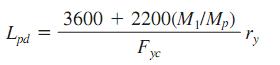
Where Fyc=minimum yield stress of compression flange, ksi (MPa)
M1=smaller of the moments, in-kip (mm MPa) at the ends of the unbraced length of beam
Mp=plastic moment, in kip (mm MPa)
Ry=radius of gyration, in (mm), about minor axis
The plastic moment Mp equals FyZ for homogeneous sections, where Z = plastic modulus, in l3 (mm3) and for hybrid girders, it may be computed from the fully plastic distribution. M1/Mp is positive for beams with reverse curvature.
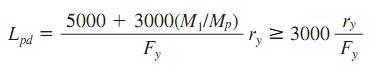
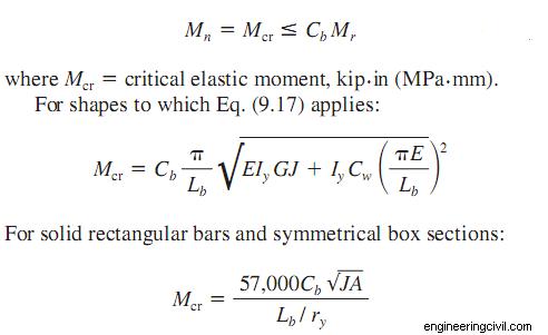
For solid rectangular bars and symmetrical box beams:
The flexural design strength 0.90Mn is determined by the limit state of lateral-torsional buckling and should be calculated for the region of the last hinge to form and for regions not adjacent to a plastic hinge. The specification gives formulas for Mn that depend on the geometry of the section and the bracing provided for the compression flange.
For compact sections bent about the major axis, for example, Mn depends on the following unbraced lengths:
Lb=the distance, in (mm), between points braced against lateral displacement of the compression flange or between points braced to prevent twist
Lp=limiting laterally unbraced length, in (mm), for full plastic-bending capacity
=300ry/( Fyf)½ ; for I shape and channels
=3750(ry/Mp)/(JA)½ for solid rectangular bars and box beams
Fyf=flange yield stress, ksi (MPa)
J=torsional constant, in 4 (mm4) (see AISC “Manual of Steel Construction” on LRFD)
A=cross-sectional area, in 2(mm2 )
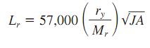
Lr =limiting laterally unbraced length, in (mm), for inelastic lateral buckling
For I-shaped beams symmetrical about the major or the minor axis, or symmetrical about the minor axis with the compression flange larger than the tension flange and channels loaded in the plane of the web:
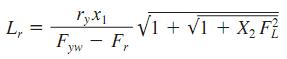
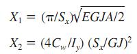
Where
Fyw=specified minimum yield stress of web, ksi (MPa)
Fr=compressive residual stress in flange
=10 ksi (68.9 MPa) for rolled shapes, 16.5 ksi (113.6 MPa), for welded sections
FL=smaller of Fyf– Fror Fyw
Fyf=specified minimum yield stress of flange, ksi (MPa)
E=elastic modulus of the steel
G=shear modulus of elasticity
Sx=section modulus about major axis, in 3 (mm3 ) (with respect to the compression flange if that flange is larger than the tension flange)
Cw=warping constant, in 6 (mm6) (see AISC manual on LRFD)
ly moment of inertia about minor axis, in4 (mm4 )
For the previously mentioned shapes, the limiting buckling moment Mr, ksi (MPa), may be computed from
Mr= FL Sx
For compact beams with Lb <= Lr, bent about the major axis:
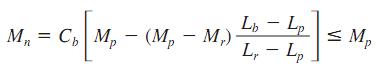
Where
Cb=1.75+1.05(M1/M2)+0.3(M1/M2) <= 2.3, where M1 is the smaller and M2 the larger end moment in the unbraced segment of the beam; M1/M 2 is positive for reverse curvature and equals 1.0 for unbraced cantilevers and beams with moments over much of the unbraced segment equal to or greater than the larger of the segment end moments.
For solid rectangular bars bent about the major axis:
and the limiting buckling moment is given by:
Mr=FySx
For compact beams with Lb> Lr, bent about the major axis:
For determination of the flexural strength of noncompact plate girders and other shapes not covered by the preceding requirements, see the AISC manual on LRFD.
If you have a query, you can ask a question here.