

Presented By
Er.T.RANGARAJAN, B.E, M.Sc(struct.engg), F.I.E, FACCE, LACI, LISSE, LIASE
WHO IS AN ENGINEER?
According to USA President Herbert Hoover, who was an engineer before he became a politician, said:
The great liability of the engineer …compared to men of other professions……is that his works are out in the open where all can see them.
His acts …..step by step …are in hard substances.
He cannot bury his mistakes in the grave like the DOCTORS.
He cannot argue them into thin air…..or blame the judge…..like the LAWYERS.
He cannot, like the ARCHITECT, cover his figures with trees and vines.
He cannot, like the politicians, screen his shortcomings by blaming his opponents….and hope the people will forget. The ENGINEER simply cannot deny he did it.
If his works do not work……he is damned.
Important Points from Presentation
A design engineer’s responsibility should include assuring the structural safety of the design, details, checking shop drawing.
Detailing is as important as design since proper detailing of engineering designs is an essential link in the planning and engineering process as some of the most devasting collapses in history have been caused by defective connections or DETAILING. There are many examples explained in the book” DESIGN AND CONSTRUCTION FAILURES by Dov Kaminetzky.
Detailing is very important not only for the proper execution of the structures but for the safety of the structures.
Detailing is necessary not only for the steel structures but also for the RCC members as it is the translation of all the mathematical expression’s and equation’s results.
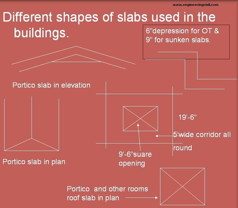
For the RCC members for most commonly used for buildings we can divide the detailing for Slabs-with or without openings.(Rectangular,circular,non-rectangular-pyramid slab,triangular etc) balcony slab, loft slab, corner slab etc
Beams – With or without openigs.(Shallow & deep beams)
Columns – (Rectangular,l-shape,t-shape, circular,octagonal,cross shape etc)
Foundations.
Detailing for gravity loads is different from the lateral loads specially for the SEISMIC FORCES.
Apart from the detailing for the above there is a different detailing required for the Rehabilitation and strengthening of damaged structures.
We will now dwell on the DETAILING OF MEMBERS FOR THE GRAVITY AND SOME CODAL DETAILINGS AS PER IS CODE IS 13920 AND IS 4326 AS REQUIRED FOR SEISMIC FORCES.
DO’S & DONOT’S FOR DETAILING
DO’S-GENERAL
Prepare drawings properly & accurately if possible label each bar and show its shape for clarity.
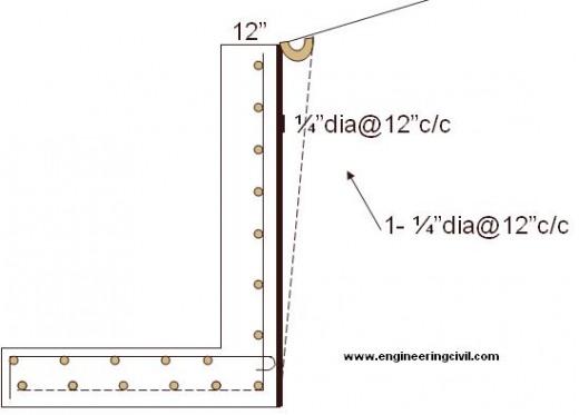
Cross section of retaining wall which collapsed immediately after placing of soil backfill because ¼” rather than 1-1/4” dia. were used. Error occurred because Correct rebar dia was covered by a dimension line.
2. Prepare bar-bending schedule, if necessary.
3. Indicate proper cover-clear cover, nominal cover or effective cover to reinforcement.
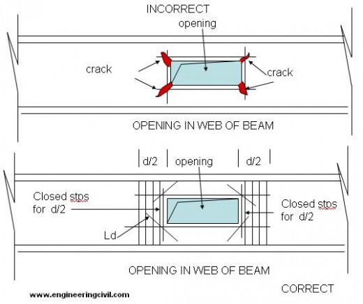
4. Decide detailed location of opening/hole and supply adequate details for reinforcements around the openings.
5. Use commonly available size of bars and spirals. For a single structural member the number of different sizes of bars shall be kept minimum.
6. The grade of the steel shall be clearly stated in the drawing.
7. Deformed bars need not have hooks at their ends.
8. Show enlarged details at corners, intersections of walls, beams and column joint and at similar situations.
9. Congestion of bars should be avoided at points where members intersect and make certain that all rein. Can be properly placed.
10. In the case of bundled bars, lapped splice of bundled bars shall be made by splicing one bar at a time; such individual splices within the bundle shall be staggered.
11. Make sure that hooked and bent up bars can be placed and have adequate concrete protection.
12. Indicate all expansion, construction and contraction joints on plans and provide details for such joints.
13. The location of construction joints shall be at the point of minimum shear approximately at mid or near the mid points. It shall be formed vertically and not in a sloped manner.
DO’S – BEAMS & SLABS:
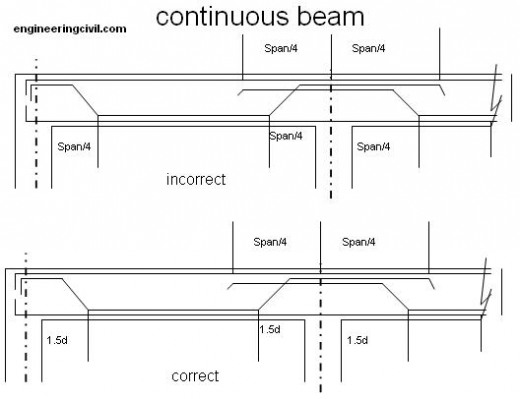
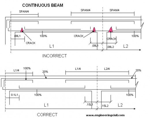
1. Where splices are provided in bars, they shall be , as far as possible, away from the sections of maximum stresses and shall be staggered.
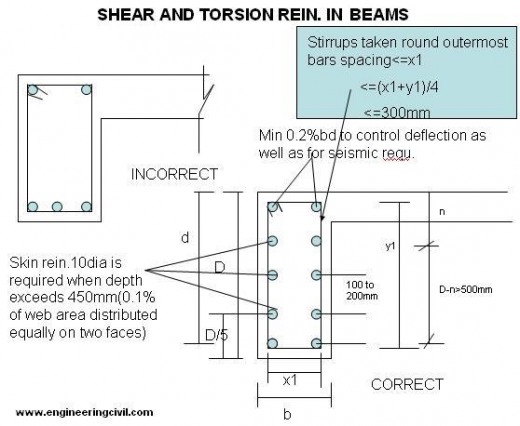
2 Were the depth of beams exceeds 750mm in case of beams without torsion and 450mm with torsion provide face rein. as per IS456-2000.
3. Deflection in slabs/beams may be reduced by providing compression reinforcement.
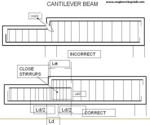
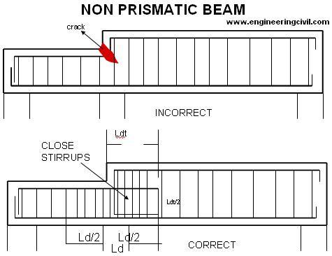
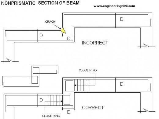
4. Only closed stirrups shall be used for transverse rein. For members subjected to torsion and for members likely to be subjected to reversal of stresses as in Seismic forces.
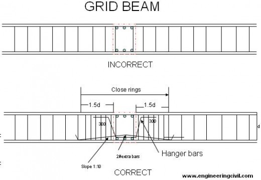
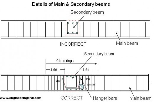
5. To accommodate bottom bars, it is good practice to make secondary beams shallower than main beams, at least by 50mm.
Do’s –COLUMNS.
1. A reinforced column shall have at least six bars of longitudinal reinforcement for using in transverse helical reinforcement.-for CIRCULAR sections.
2. A min four bars one at each corner of the column in the case of rectangular sections.
3. Keep outer dimensions of column constant, as far as possible , for reuse of forms.
4. Preferably avoid use of 2 grades of vertical bars in the same element.
DONOT’S-GENERAL:
1. Reinforcement shall not extend across an expansion joint and the break between the sections shall be complete.
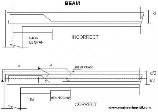
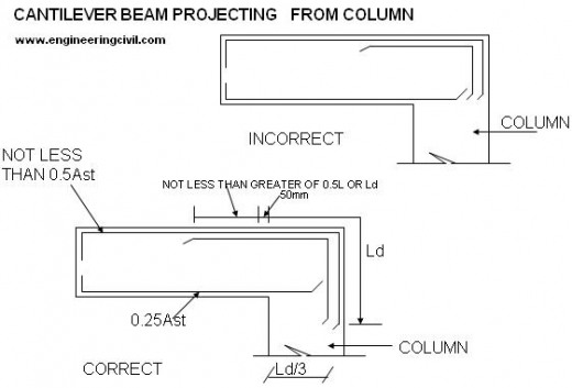
2. Flexural reinforcement preferably shall not be terminated in a tension zone.
3. Bars larger than 36mm dia. Shall not be bundled.
4. Lap splices shall be not be used for bars larger than 36mm dia. Except where welded.
5. Where dowels are provided, their diameter shall not exceed the diameter of the column bars by more than 3mm.
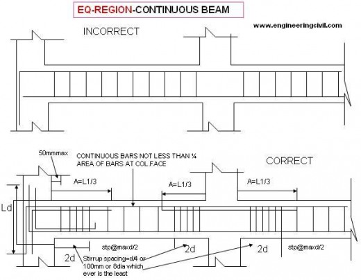
6. Where bent up bars are provided, their contribution towards shear resistance shall not be more than 50% of the total shear to be resisted. USE OF SINGEL BENT UP BARS(CRANKED) ARE NOT ALLOWED IN THE CASE OF EARTHQUAKE RESISTANCE STRUCTURES.
DETAILING OF SLABS WITHOUT ANY CUT OR OPENINGS.
The building plan DX-3 shows the slabs in different levels for the purpose of eliminating the inflow of rainwater into the room from the open terrace and also the sunken slab for toilet in first floor.
The building plan DX-A3 is one in which the client asked the architect to provide opening all round.
Minimum and max.reinforcement % in beams, slabs and columns as per codal provisions should be followed.
SLABS:
It is better to provide a max spacing of 200mm(8”) for main bars and 250mm(10”) in order to control the crack width and spacing.
A min. of 0.24% shall be used for the roof slabs since it is subjected to higher temperature. Variations than the floor slabs. This is required to take care of temp. differences.
It is advisable to not to use 6mm bars as main bars as this size available in the local market is of inferior not only with respect to size but also the quality since like TATA and SAIL are not producing this size of bar.
BEAMS:
A min. of 0.2% is to be provided for the compression bars in order to take care of the deflection.
The stirrups shall be min.size of 8mm in the case of lateral load resistance .
The hooks shall be bent to 135 degree.
DEVELOPMENT LENGTH OF BARS FOR A CONCRETE GRADE M20 &STEEL STRENGTH Fy=415
|
SLNO
|
BAR DIA.
|
TENSIONmm
|
COMPRESSION
|
REMARKS
|
|
1
|
8
|
376.0
|
301.0
|
|
|
2
|
10
|
470.0
|
376.0
|
|
|
3
|
12
|
564.0
|
451.0
|
|
|
4
|
16
|
752.0
|
602.0
|
|
|
5
|
20
|
940.0
|
752.0
|
|
|
6
|
22
|
1034.0
|
827.0
|
|
|
7
|
25
|
1175.0
|
940.0
|
|
|
8
|
28
|
1316.0
|
1053.0
|
|
|
9
|
32
|
1504.0
|
1203.0
|
APPROXIMATELY USE 50Xdia FOR TENSION
References:
1. Handbook On Concrete Reinforcement And Detailing-sp:34(s&t)-1987.
2. Manual Of Engineering & Placing Drawings For Reinforced Concrete Structures- (Aci 315-80
3. Manual Of Standard Practice –concrete Reinforcing Steel Institute.
4. Tward Board Manual For Rural Water Supply Schemes.
5. Design Principles And Detailing Of Concrete Structures. By D.S.Prakash Rao.
6. Simplified Design-rc Buildings Of Moderate Size And Height-by Portland Cement Association,Usa.
7. Design And Construction Failures By Dov Kaminetzky.
8 IS:2502-1963 Code of practice for bending and fixing of bars for concrete reinforcement.
9. IS:1893:2000.
10. IS:4326.
11. IS:456:2000
12. Reinforced hand book by Reynold.
Download the Presentation on Reinforcing Detailing Of R.C.C Members
We are thankful to Er.T.Rangarajan for enlightening some of the detailing technique for the most commonly encountered RCC members in buildings. This presentation will surely help engineers to learn the reinforcement detailing of RCC members.
If you have a query, you can ask a question here.
Res.Sir
Please let me know junction concreting of following circumstancis.
1. when col.grade is M40 & beam & slab grade is M30.
how will have to do concreting when col. & beam meet each other on each level of floor?
Thank you
Regards
Dear sir,
What is the purpose in concrete design mix for (1.65 & standard deviation) please tell me i’m wait for ur reply.
what is the soil test procedure & purpose in DRU DENSITY,DEGREE OF COMPACTION,PLASTIC LIMIT,LIQUIT LIMIT,PLASTIC INDEX,GRADING ANALYSIS.
Just I appreciate from this site.
Dear WebSite.
Love your presentation.
Dear Sir
I want to know how development length is calculated for different grade of concrete,& also for members in tension & compression?
If you provide me the right answer i shall be highly obliged.
Thanks & Regards.
M S Khan
Development length depends on Grade of Concrete & stress in steel at that particular section. It is more for Lower Grade of Concrete & Higher Grade of steel and also More for Bars in tension than in Compression.
For Avergae M-25 Conc for bars in Tension this can be rounded to 45 d & 40 d in Compression.
You may refer a Standard Design Book based on Limit State of Design for more details.
very much useful for getting valuable information in respect of practical point of view.
if it is incorporated with the practical problems arising in site then more learnings will benefited from this site
thanks for ur nice work. this is really help full for practical construction work
very much useful information, thanks for ur nice work. this is really help full for practical construction work and for new structural engineers
sir its all about a general building ?what about other buildings?
helped me alot for making presentation…..very useful information gained frm d site.
thanxx..
While detailing out Beam Column Junctions as per IS 13920 there are practical difficulties of Providing End Anchorages in cases where Columns & Beams have same widths specially in Residential Buildings. What is the practical way out to avoid such congestion where practically Concrete mix can not enter?
very effective in detailing of structures
I must commend your efforts in creating sites like this that can be useful to an 0’level civil engineering student. I have learnt much today from this site on my first visit to this site. I have been having problems in my approach to concrete structural detailing but i think that this problem that seemed to have an endless solution has been properly solved. Please keep up the good work. WE MUST HARNESS THE EARTH FOR MAN’S COMFORT!!!!
Hardcore information site for construction field.
Really good work.
Reg,
Dear sir,
Can u pls tell to where to provide laps and cutting of bar for following beam:-
size of beam 500mm X 900mm
Lengths:-col In to col in = 12.51m.
Col out to col out = 13.71m.
size of col at ends = 600mm X 600mm
Steel details :- Top steel = 16mm dia.-4 Nos.
Top EOS =25mm dia.-3Nos. at col ends only.
Btm bar=25mm dia.-4Nos.
Btm EOS = 25mm dia.-4Nos at full length of beam.
Kindly provide location of lap for all steel bar.
Thanks,
how do i get the value of Ld and Ldt
goood work…….
tell me something about bending allowances in beam,slab
How will differentiate between RCC Column & RCC Shear wall w.r.t. Size. or Length & width ratio ? Is their any ref. in IS Code ?