

By
Fawale, Babatunde Lawale
Ajayi, Johnson Oluwafemi
Oyedemi, Peter Oluwatosin
ABSTRACT
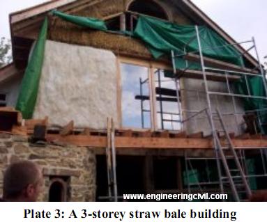
This project is an evaluation of the effectiveness of strawbale in building construction. It introduced the use of straw, which when baled could be used as a resource, that is, as a walling material, more economically than other conventional walling materials.
This study shows the edges that strawbale has over other conventional walling materials (sandcrete block), thermal insulating property, availability ease of construction, economical amongst others. The minimum plaster thickness (coating) which when applied to the strawbale wall that can give the optimum strength was found to be 15mm this is obtained from compressive strength test.
It also displays the graphical representation of the thermal insulation tests carried out on the two prototype buildings (strawbale and sandcrete block), in which strawbale building retained more heat than the sandcrete block building.
1.0 INTRODUCTION
1.1 BACKGROUND OF THE STUDY
The need to construct buildings with viable low cost material has become a necessity in our fast growing society. It goes without saying that the growing population of the people of Nigeria (most populous black nation on earth) and the escalating cost of conventional building construction materials is now a problem in the housing sector. With this in mind, there is need to look for alternative, which have to be cost effective and readily available. Hence, the need for this study.
A material that meets up with such requirements is straw bale. Straw bale construction is a method of building that incorporates the use of straw bales as structural elements. It has been found to be suitable for living houses, offices and other purposes.
Straw is the springy tubular stalk of grasses like wheat, rice, sorghum that are high in tensile strength. It is not hay, which is used for livestock feeding and includes the grain head. Straw is composed of cellulose, hemi-cellulose liquid and silica. It is non rigid it is flexible and easy to work with.
Bales are masses of straw compressed into rectangular blocks and bound with steel wire or propylene twine.
The typical straw bale is bound with two or three strings of polypropylene twine though sometimes wire or fibre twine is used, and it is relatively easy for one man or woman to handle. In other words bales as farmers have always made them are generally just fine for construction. The biggest concern for bale holders is the type of combine used to harvest the straw -conventional combines that leaves long straw fibres (which is good for building), and rotary combines that chop the straw into short fibre (which makes for unstable crumbly bales).
With the increased industrialization of farms, other types of the bales are beginning to predominate in many areas:
1. Jumbo bale: Rectangular blocks bound with six to ten string of a typical size like 3ft x 4ft x 8ft (1m x 1.3m x 2.2m), which can only be handled by mechanized equipment.
2. Circular bales: Disks bound with twine of typical dimension 3ft thick and 6ft in diameter. Also machine handled.
3. Super compressed bales: Ordinary bales compressed to roughly twice the original density.
There are two primary ways of building with straw bales.
i Load bearing or Nebraska style.
ii Post and beam / In – fill / non- load bearing method
In load bearing straw bale construction, bales are stacked and reinforced to provide structural walls that carry the roof load. While in post and beam method, a wood, metal or masonry structural frame supports the roof and bales are stacked to provide non- structural in insulating walls. With either alternative, the bale walls are plastered or stuccoed on both the interior and exterior of the wall. The study will be based on the former. The load bearing straw bale construction employs relatively simple techniques that are forgiving to novice builder and yet have sufficient flexibility to allow the creation of design features such as curved walls.
Moreover, a straw bale demonstrates excellent insulative properties such as thermal, sound and fire resistance. Also the structural capacity of the straw bale construction is surprisingly good. It should be added that the technology of straw bale construction is still rapidly evolving .It is highly rated for ‘buildability’ because it can be very straightforward. And it is important to keep bales during storage and construction and to try and eliminate vermin. During construction, tarpaulins or plastic sheets should be kept ready for covering otherwise up protected walls. Although it may not be dried if bales do get wet slightly, they can often be dried out sufficiently to be usable.
Lastly, it has been found that straw bale walls are very resilient and in the event of damage they can be repaired. Wet bales can be taken out and replaced. (Harvest Homes; 2004)
1.2 AIMS AND OBJECTIVES
i. To evaluate the Compressive Strength of straw bale as a walling material. (Plastered straw bale wall and unplastered straw bale wall).
ii. To assess the thermal insulating property of Straw bale in building construction.
iii. To carry out comparison of thermal insulating property between straw bale and sandcrete blocks.
iv To establish the ease at which straw bale material can be used in building construction.
v. To make appropriate recommendation.
1.3 SCOPE
– Evaluation of the strength of straw bale (load – bearing type) in building construction.
– Determination of the plaster thickness that can be applied on straw bale wall.
– Assessing thermal Insulation as a property in straw bale building construction.
– Comparative evaluation of thermal insulating property of straw bale and sandcrete block.
– Comparison of the cost of using straw bale in building construction to sandcrete block.
1.4 METHODOLOGY
Basically, this research work will require getting samples of straw from local source and compressing it to form bale. Comparative test will be carried out by constructing a prototype enclosed wall using straw bale and sandcrete block; thereby authenticating basic properties such as strength, thermal insulation, fire resistance e.t.c Thus, further search will be made to evaluate the affordability of straw bale in terms of its cost.
2.0 LITERATURE REVIEW
2.1 HISTORICAL BACKGROUND ON STRAW BALE
Straw is one of the finest renewable building materials available and is found around the world in abundance. It is the strong stalk of tall grain plants such as guinea corn, maize, wheat, hemp, rye or rice that remain in the field after the seed grains have been harvested.
Its chemical composition is primarily cellulose, just like trees. When bundled together into a bale it becomes. Solid block that is highly resistant to decomposition. When assembled together and covered with a plaster skin, straw bales make a beautiful, strong, energy – efficient and ecologically sound house.
Early settlers of the grasslands of Nebraska and Western Canada discovered the beauty of building with straw bale over 100 years ago. Necessity is the germ of their discovery. Confronted with cold winters a
lacks of trees and a need for a quickly built out – building, the settler turned to the abundant straw to house their animals. They piled the bales, put on a roof and added earthen plaster. The result was superb. The insulation against the cold was found and exceeded any wood building. They then proceeded to build their homes with straw bales too. In fact, many of the original settlers’ farm buildings and homes are still intact standing as a testament to the materials strength and longevity. (Harvest Homes coy, 2003).
Contemporary builders are waking up to its virtues too. With every year, people around the world are discovering the benefit of buildings with the straw bales (Harvest Homes Company Journal, 2003.).
2.2.0 MATERIAL PROPERTIES
The choice of building construction materials is governed largely by the properties of the materials that are pertinent to what the builder has in mind. Straw bale as a construction material is not an exception.
2.2.1 THERMAL INSULATION
Straw bale demonstrates excellent insulative properties; it is possibly the most cost effective thermal insulation available. Straw has a similar insulation value to fiberglass batts. Straw bales wall has insulation value that greatly exceeds that of any conventional construction. Downton (2003).
Likewise, Adedeji (2007) said ‘all new building must be energy efficient with straw walls; the insulation (straw) is also the building block.’ Also, Lee (2001), said “Straw compacted into bales offers much better insulation with its high thermal resistance”.
2.2.2 SOUND INSULATION
Paul Downton (2003),stated that ‘the effect of sound insulation contributes to the livability of straw bale construction and can be quite marked. Even walking into the space created by an unfinished straw bale structures, one can appreciate the quietness and hear the difference compared with conventional building.
In the same vein, Adedeji (2007) said “there is over-whelming experimental evidence that straw walls offer far more sound insulation than 20th century wall building materials”.
2.2.3 STRUCTURAL STRENGTH
Unlike wood from construction that has low tolerance to extreme lateral and lift force such as tornadoes or earthquakes. Straw bale building’s continuous monolithic plaster provides extra ordinary strength and elasticity in the face of such force. They can actually flex and bend, but resist collapse making straw bale building ideal for quake, hurricane or tornado prone areas. (Harvest Homes, 2003).
2.2.4 FIRE RESISTANCE
Straw bale are lightly packed and covered with a skin of cement render. Fire cannot burn without oxygen and the dense wall provides a nearly airless environment. So the fire resistance of compacted straw is very good. Conclusive evidence of its good fire resisting performance can be found in laboratory fire tests conducted at the Richmond field station in 1997 by students at University of Berkeley. These rated a straw wall at 2 hours. Straw bale home survived Californian burn fire that destroyed conventional building.(Downton, 2003).
Adedeji (2007), said it is popular misconception that straw bale buildings are a fire risk. In a fire, its chars on the outside and then the charring itself protect the straw from further having. When the wall is plastered in both sides, the risk of fire is reduced.
Compactness of the straw, combined with plaster coating does not provide air to support combustion. Canada Mortgage and Housing Company (C.M.H.C) demonstrated a lower fires risk when compared to conventional construction materials and method, straw bale walls came out with 2 hours or commercial fire rating (Harvest Homes, 2003).
2.2.5 MOISTURE RESISTANCE
Paul Downton (2003) profers that provided the straw is reasonably well protected and is not allowed to become water logged, it can last many years with moderate maintenance. Bales during construction should have moisture content not exceeding 15% and not below 10%. Straw bales should not get wet inside, should it be wet it will not be a problem since straw does not wick water like concrete. If rain is driven into the sides of bales the natural air movement around the bales is able to dry them out and this cycle of wetting and drying does not damage the bale.
The California straw bale code (2001) asserted that the moisture content of the bales at the time of installation should not exceed 20% of the total weight of the bale.
2.2.6 PEST RESISTANCE
Straw is ideal for areas at high risk of termites since it does not suit their palette. (Harvest Homes, 2003).
2.2.7 COST AND AVAILABILITY.
Straw bale is a low cost material. It is readily available of an affordable cost. It is can be obtained from both near and far sources.
2.3.0 STRAW BALE CONSTRUCTION PROCESS
Straw bale construction is still a very much a developing technology, nonetheless, a distinct trend has become apparent: There are two basic styles of construction, the load bearing in which the weight of roots and entirely by bales; and the post and beam straw bales is that in which bales are used as in-fill panels between or around structural frame of any structural materials.
Emphasis will be laid on the former in this study. A little will be discussed on the construction process
2.3.1 FOOTINGS
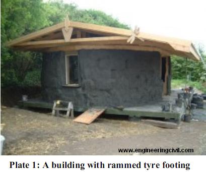
A straw bale wall requires footings with a similar load – carrying capacity to that required for a masonry wall, although a straw wall is lighter (one mud brick weights about the same as a straw bale.). The footings usually used are concrete strips or slabs. There have been successful experiments with rubble trench and rubber tyre footings and there are several straw bale buildings built on piers, beam and joist. (Paul Downton, 2003).
The California straw bale code (2001), has it that support for bale walls shall extend to an elevation of at least six inches above adjacent ground at all points, and at least one – inch above floor surfaces.
King (2001) opines that the bottom of the bale wall must be well separated from the foundation and at the very moisture water- proof barrier should be laid over moisture below. Additionally, many builders are placing a layer of pea gravel between wood sill plates along the inside and the outside faces so that bales will never be sitting in water.
Likewise, California straw bale code (2001) recommends that, a moisture barrier shall be used between foundation top and the bottom of bale walls to prevent moisture from migrating through the foundation so as to come into contact with the bottom course of bales.
2.3.2 BALES STACK UP
Typically, the bales are stacked in running or stack bond on top one another; early experiments with adding cement mortar between courses created thermal bridges while giving no clear benefits. In load bearing building, the bales are laid flat, that is with the longest dimension parallel to the wall and the shortest vertical. In other application, the bales can be stacked on edge that is with the shortest dimension horizontal. This saves interior space with slimmer wall, and, interestingly appears to offer the same net insulation value due to the slightly different orientation of the fibers. (Bruce king, 2001).
In the same vein, the California straw code holds the view that in load bearing walls of bale, bale should be laid flat and be stacked in a running bond, where possible with each bale overlapping the two bales beneath it. Overlaps shall be a minimum of 12 inches.

2.3.3 STRAW BALE WALL HEIGHT
Australia straw bale expert’s recommends a maximum wall height of 2.5 meters when using standard sized bales in load bearing construction. The California straw bale code (2001) has it that building with load bearing bale walls shall not exceed one story height without substantiating calculations and design by a California civil engineer, and the bale portion of the load bearing walls shall not exceeds a height to width ratio of 5.6:1 (for example the maximum height for a wall that is 23 inches thick would be 10 feet 8 inches or 3.27 meters).
Whereas, the harvest homes (2003) holds the view that “ given that straw bale walls have been shown to be at least 4 times stronger than a conventional 2×6 frame wall there are no special limitation to the heights of a building.
2.3.4 PLASTER
The California straw code (2001) has it that minimum bale thickness shall be 13inches. Also plaster can be lime-gypsum, lime – cement plaster. Bruce king (2001) held the view that it is essential that, once plaster is
applied directly to either or both of the straw bale surfaces, the completed wall assembly is now a hybrid of straw and plaster, in other words a sandwich panel. Plaster is used generically to include traditional earthen
plasters, lime and gypsum plasters shot Crete or gucite, cement stucco.
Also, Paul Downton (2003) said “ that three layers of render should be progressively ‘weaker’ to reduce the potential for cracking caused by having too brittle an external layer.

2.3.5 PINNING
Straw bales are comparatively soft and do not behave like bricks. Except when surrounded by a sturdy frame of post and beam the bales must be braced or pinned during stacking for stability and alignment. Internal pinned of the walls (with bamboo or dowels) has been prescribed in early straw bale codes, but it as falling out of favour, for it is under whether internal pins contribute appreciably to the strength of the finished wall assembly. Bruce king (2001).
Likewise, Downton (2003) said ‘the vertical and horizontal stability of straw bale walls generally needs to be guaranteed by tying bales to structural frames or pinning between bales and structural elements, however there is a growing consensus that the extensive use of reinforce steel bars and excessive pinning that characterized early straw bale construction is not necessary.
2.4.0. BASIC TESTS ON STRAW BALE
2.4.1 THERMAL INSULATION TEST RESULT
Adedeji, A (2007) has it that the u-value or thermal transmittance of a material the amount of heat transmitted per unit area of the between inside and outside environment. It is measured in watt per square meter per degree of temperature difference (Kelvin) N/m2k. Simply put, it is a measure of how much heat materials allows to pass through it. The lower the u – value, the greater the insulation of the materials.
The tables below display the comparison of u-value of straw with other materials and the result of analysis for different types of straw.


2.4.2 Test On Plastered Bale
Zhang John (2002) carried out “ Load carrying characteristics of a single straw bale under compression. Two–string wheat bales were tested flat and on edge, plastered and unplastered, in some cases under low
frequency cyclic loading.
Both cement and earthen plasters were tested, there were two weeks between cement coats with average thickness of 1.6”. From the test, the following were observed.
i. There is an initial set phase of the test in which the ‘fluff’ between bales is compressed; the author identified this as 3 to 4% of height. In other words, at least for this particular bales 3 to 4% of its height
before plastering.
ii. There is always a delayed effect on the recovery of the deformation as the unplastered straw is unloaded.
David Mar. (2003), carried out test on the bearing capacity of plastered straw bales. Rice straw half- bales were fabricated and stacked flat giving a cross section of 23” x 23” plus 1.5” plaster skin each side. Plasters were cured at least one month and load was applied via a stiffened plywood plate covering the plaster edges; ultimate loads were recorded as follow.
Lime – cement stucco w/2” x2”x14 gauge mesh/avg of 3:2810lbs12.5ka) High straw fibre earthen plaster w/ coconut fiber mesh /avg of 3:2340lbs10.4480). Low straw fiber earthen plaster w/coconut fibre mesh/
avg of 2 1575lbs(7kw).
2.5.0 APPLICATION
Today, straw bale building has become very popular. Everything from garden, Sheds, cottages, studios, modest houses, grand mansions to large commercial building can be found in most Canadian provinces united states, Mexico, Australia, Europe and far beyond.
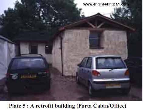
They are also ideal for retrofit applications. It has been used as wrap on the exterior of old, poorly insulated houses or in the interior of large commercial building for warehouses in order to dramatically improve energy
efficiently.
3.0 METHODOLOGY
3.1.0 UNIT DENSITY AND DRY UNIT WEIGHT
Weight of Six consecutive plastered straw bale prisms were measured with weighing balance and the dry unit weight were determined.
Plastered straw bale unit density is the gross density of the complete dry plastered straw bale mass divided by its gross volume. This is done with a view to knowing the load the sample can carry and handling requirements.
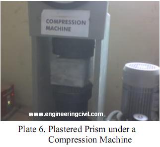
3.1.1 COMPRESSIVE STRENGTH TESTS
This is the performance of plastered straw bale wall under loading with varying plaster thickness. The modes of failure of the six prisms were noted.
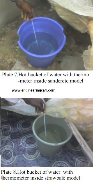
3.1.2 THERMAL INSULATION TEST
The thermal insulation test was carried out on a prototype straw bale building and sandcrete block. Built in the open with and the same floor area of 1.sq.meter and identical floors and roofs.
A bucket of containing 10 litres of hot water at say 65- degree centigrade was put into each of the prototype buildings. The roots of the models were then wrapped with thick polythene to prevent the loss of heat through the roof opening. The temperatures of the each of the models were taken at regular intervals with thermometer to ascertain the heat losses in each model.
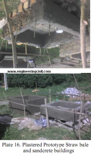
3.2.0 CONSTRUCTION OF PROTOTYPE PLASTERED STRAW BALED WALL
3.2.1 MATERIALS USED FOR CONSTRUCTION
The construction of a prototype straw bale wall will be carried out with the following materials. Mature straw of guinea corn stalks (cut to size and baled) ordinary Portland cement, fine aggregates, steel wire/ twine, wire mesh and water.
3.2.2 MATERIAL QUALITY AND ACQUISITION
Guinea corn is the straw type used in this project. It was left in the open space to dry for several weeks after acquisition from a local farm. The straw is clean, free from debris and other leaves. This is usually obtained between December and February when farmers are preparing to clear their farms for the raining season.
Ordinary Portland cement was used and mixed with water fit for drinking, clean, contaminant free, and free from organic material, coupled with dissolved or suspended solid which could affect the mortar strength
adversely.
The fine aggregate used was clean, soft, well -graded natural sand free from salt and organic contaminants.

3.3.0 CUTTING AND BALING OF STRAW
The straws were cut to size 120mm using cutlass and were held together with wooden battens. Compressive strength machine was used in lieu of baling machine, since it is not reputed to be available in Nigeria. The baled straws were compressed and tightly bound with twine. This was done to avoid looseness, thus, increasing the density of bale.

3.4.0 BATCHING
Proportioning of cement to fine aggregate mix can either be done by volume or weight. As far as this project is concerned, batching was made by weight. The mix ratio adopted is 1:8, that is one part of cement to eight parts of fine aggregate.
3.4.1 MORTAR MIXING
Mixing of mortar may be done manually or mechanically. Here, mixing is done manually using shovel, the mixture of cement and sand was done twice dry and twice wet thoroughly.
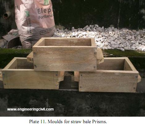
3.5.0 MOULD FOR STRAW BALE PLASTER PRISMS
Construction of wooden moulds of inner sizes of 80mm x 120mm x 200mm, 110mm x 150mm x 230mm and 140mm x160mm 240mm for plastered straw bale prisms and different mould were constructed according to variation in plaster thickness of 10mm, 15mm and 20mm.
For easy removal of the specimen, lubrication oil and polythene were used
3.5.1 STRAW BALE WALL LAYING
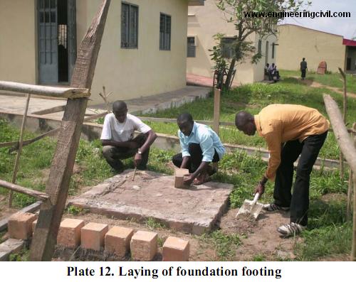
The foundation footing was laid in trenches by pouring concrete in it. Then wooden joist (150 x 150mm) were laid on the concrete footing and floorboards were laid across. Thereafter, a stud is driven into the joist vertically this could be bamboo.
Afterwards, the bales were stacked in a running or stack bond flat, directly a top one another that is, the longest dimension parallel to the wall and the shortest vertical.

3.5.2.0 CONSTRUCTION OF PROTOTYPE SAND CRETE BLOCK WALL
3.5.2.1 MATERIALS USED FOR CONSTRUCTION
The construction materials are sharp sand and ordinary Portland
cements and water.
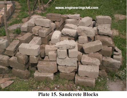
3.5.2.2 MOULDING OF SAND CRETE BLOCKS
The cement and sharp sand used was batched by volume 1:8 mixed to a dry and twice wet it was then placed into steel moulds (100 x 100 x 200mm size) rammed. Thereafter it was sieved for seven days.
3.5.2.3 LAYING OF SANDCRETE BLOCKS
After digging of trenches, foundation was laid. Afterwards, the blocks were laid on the stretcher side up to seven courses.
3.5.2.4 RENDERING AND PLASTERING OF SANDCRETE BLOCKS
The fine sand was sieved and batching was carried out by volume (1:8). Both cement and sand) were mixed well with water and the water is applied the walls’ surface and smoothened.
3.5.3 PLASTERING OF STRAW BALE
The straw bale wall was plastered with the aid of hand trowel. It was worked in to the bale surface, inside and outside layers and it was given a smooth finish.
Also, for the compression tests, the bales are encased in mixed mortar placed in mould and compacted to eliminate voids. Prior to this chicken mesh cut to size, placed as the stretcher side of the bale to reinforce the plaster skin.
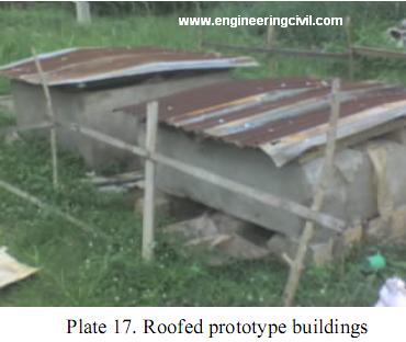
3.5.4 ROOFING OF PROTOTYPE BUILDINGS
The materials used for the rooting are: plank {2” x2”, 2 x4” and 2” x4”), corrugate iron sheet and nails. The some materials were used for both buildings. Roof structure was constructed with a gentle slope to give room for minor headroom.
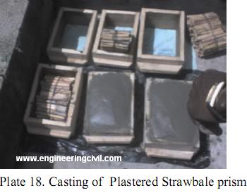
3.6.0 CASTING AND CURING OF PLASTERED STRAWBALE PRISMS
Fine aggregate and cement were batched by volume in the ratio 1:8, they were mixed thoroughly dried and with water. Thereafter, the hated straws (80 x 120 x 200mm) were placed inside the mould(s) and wire mesh was provided at the stretcher faces. The mould was then filled up with the mixed mortar with thickness varying according to sizes of the moulds, see plate 18.
The prisms were demoulded the following day and they were cured.
The curing method adopted is the blanket type, in which dry straw was spread over the plastered straw bale surface. This is to provide insulation and act as moisture holding medium, the specimens was wetted
for 7 days and were left for 28 days, ready for testing.
3.6.1 SCALE FACTOR FOR PLASTERED STRAW BALE
Scale factor shows a geometric relationship between a model and a prototype straw bale. This is taken as 1/5 model of 584.2×406.4×1066.8mm size.
3.7.0 COST AND AVAILABILITY
In actual term, cost of bales varies from one place to another. The cheapest way to buy bales may be from the field after they have been made or differ harvest by farmers. In Nigeria buying directly from farmers may be very easy, while some will be willing to give it away without any attached cost. Since it will save them the stress of clearing the stalks after harvesting.
It should be noted however, that straw is present everywhere, the cost incurred will to an extent depend on the nearness to the source, the cost may be attached to means of transporting, if to the site, baling and stacking etc.(A.A. Adedeji.). Thus, if compared with the cost of conventional material like local bricks. Builder, who employ bale in his construction will safe a huge sum of money than if he had made use of bricks and other materials.
4.0 RESULTS AND DISCUSSION
4.1.0 RESULTS ON PLASTERED STRAW BALE PRISM
Sequel to the test carried out on the 28- day plastered straw bale prisms, the Results are presented in the following subsections.
4.1.1 UNIT DENSITY OF PLASTERED STRAW BALE PRISM
The unit density of the cured-plastered 28- days prism is obtained by dividing its unit mass by the gross volume.
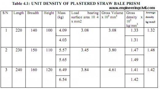

From Table 4.1. above it can be observed that the mass of the plastered straw bale prism increases with increase in plastered thickness (10-20mm). While the density increases first, from (10-15mm) then falls at 20mm plastered thickness. Thus optimum density can be obtained at 15mm thickness of plaster on straw bale.
4.1.2 COMPRESSIVE STRENGTH TEST
This test was carried out on the six plastered straw bale prism at 28-day. Each of the prisms with varrying plaster thickness was loaded to failure. The failure points were noted for each of the prism.
Likewise, the mode of failure for each of the six prisms was found to be global buckling type that is the prism bent and broke. This is the behavior of a typical wall that is well built, but with eccentrically applied load, bending was induced. See plate 19.
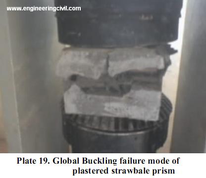
Table 4.2 COMPRESSIVE STRENGTH TESTS RESULTS ON PLASTERED STRAW BALE PRISMS
| Sample property | 1 | 2 | 3 | 4 | 5 | 6 |
| Volume of sample(mm3x105) | 30.8 | 30.8 | 30.8 | 30.8 | 46.1 | 46.1 |
| Bearing area of sample (mm2x104) | 30.8 | 30.8 | 3.45 | 3.45 | 3.84 | 3.84 |
| Dry weight of sample (kg) | 4.09 | 4.03 | 5.57 | 5.65 | 6.49 | 6.54 |
| Dry density of sample {/gmm3) | 1330 | 1310 | 1470 | 1490 | 1410 | 1420 |
| Land of failure (KN) | 15.00 | 14.50 | 20.00 | 20.50 | 40.00 | 35.50 |
| Compressive strength (N/mm2) | 0.49 | 0.47 | 0.58 | 0.59 | 1.04 | 0.92 |
| Average compressive strength (N/mm2) | 0.48 | 0.59 | 0.98 | |||
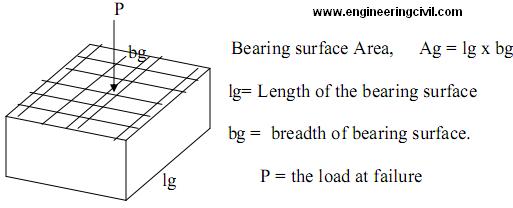
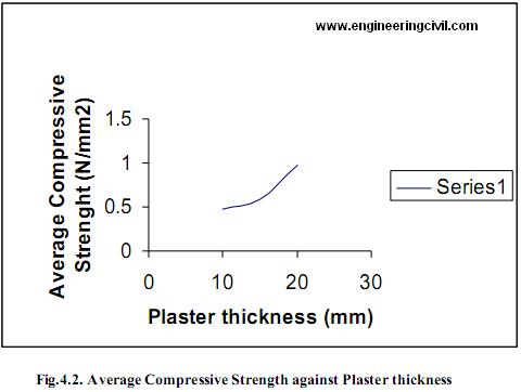
figure 4.2 above it was found out that the more the average thickness of the plaster, the more the average compressive strength, with 20mm thickness having 0.98N/mm2 maximum.
So, any plaster thickness from 15mm to 20mm was providing to be stable. See fig 4.2, the 10mm-15mm is almost flat, while the 15mm-20mm is more inclined.
4.2.0 THERMAL INSULATION TEST ON PROTOTYPE PLASTERED STRAW BALE BUILDING AND PLASTERED SANDCRETE BLOCK BUILDING
The inside temperature of the two prototype buildings were taken as intervals for 48 hours with both a thermometer for each subjected to same condition.
TABLE 4.3: INSIDE TEMPERATURE (OC) OF STRAW BALE AND SANDCRETE BLOCK BUILDING MODELS EXPOSED TO SIMILAR CONDITION
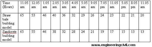
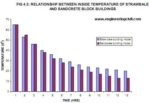
From table 4.3, the temperature of the water dropped about 10 degrees in the first hour. The temperature in the straw bale model fell slightly faster because the render inside it was absorbing heat. However during the second hour there was more heat loss from the sandcrete model.
5.0 CONCLUSIONS AND RECOMMENDATION
5.1 CONCLUSION
The following conclusions can be reached from the basic test carried out.
5.1.1 Unit density test
Below are the conclusion reached on unit density test from table 4.1.
1. The gross density of straw bale wall increased with increasing thickness (10-15mm) and fall at 20mm it is due to increase in volume which affects the gross density.
2. Optimum density can be attained at plaster thickness of 15mm.
3. Above 20mm plaster thickness; gross volume increased causing reduction in the gross density.
4. Thus, for economy 15mm thickness of plaster is desirable.
5.1.2 Compressive strength test
From table 4.2 and figure 4.1
1. The compressive strength increased with increasing plaster thickness.
2. The maximum average compressive strength is attained with the 20mm plaster thickness.
3. The behaviour of the six prisms at failure is global buckling.
In which the prism bent approvable broke. This shows that if the straw bale were well arranged stalled, it will only bend due to eccentrically applied load.
5.2.0 RECOMMENDATIONS
Based on the results of the various tests and observations the following are the recommendations:
1. For comfort, straw bale as a walling material is recommended, owing to its thermal insulating properties
2. Since straw is readily available, it is cost- effective as a walling material.
3. With the ease of construction, the straw bale as a walling material is recommended.
4. For ease of maintenance straw bale is recommended
5. It is recommended that 15mm plaster thickness when applied both sides of the wall will give Optimum Compressive Strength.
6. Straw bale is recommended for Load-bearing walls, Non-load bearing walls, Retrofit structures, Farm building, and Block of Offices, Garages amongst other applications.
7. It is recommended that further research be carried out on the Sound insulation properties, Fire resistance and the Durability of straw bale .
REFERENCES
1. Adedeji A.A, 2007, Introduction and design of straw bale masonry, Olad publishers Ent., Ilorin
2. California straw bale building code, 2001. HS18944
3. Downtown.P, 2003, Australia straw bales. Australia, www.ausbale.org.
4. Harvest Homes company, 2003 Canada, www.harvesthomes.ca
5 King, B. 2003, Load – bearing straw bale structures, U.S.A www.ecobuildnetwork.org/strawbale
6. Lacinski,P.,and Bergeron,M. 2000, serious straw bale; a home construction guide for all climates. Chelsea Green publishing coy. U.S.A
7. Lee, F, 2001, Straw bale construction, U.S.A www.uheac.org/links.html
8. Myhrmam, M, MacDonald, S, 1997 Build it with bales
We are thankful to Sir Fawale, Babatunde Lawale for submitting this report to engineeringcivil.com and also granting us rights to publish it on web. This report will help all civil engineers Evaluate the Effectiveness Of Strawbale As A Building Material.
If you have a query, you can ask a question here.