

By
Sourav Dutta
Manager-Civil
Brand embossing
On rebar pieces, different items are encrypted in the following manner:
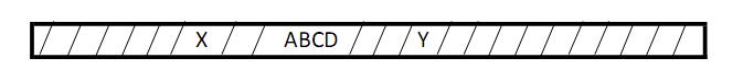
Here, X = Dia of rebar in mm, eg, 20
ABCD = Brand of rebar, eg, TATA TISCON / SAIL / JSPL etc
Y = Yield stress of rebar, eg, 500 indicates Fe500 with yield stress=500 Mpa
Chemical composition test
LSA, i.e, ladle sample analysis is done in LD and details are recorded.
TPA, i.e, test piece analysis is done at chemical lab.
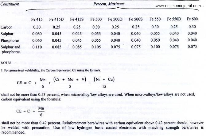
The chemical composition analysis must confirm to Amend 1 of Cl. 4.2 of IS 1786-2008 given below:
Main physical property tests for a particular rebar are as follows:
1. Tensile test : Nos of rebar sample =4, length of rebar sample =about 600 mm
2. Bend test : Nos of rebar sample =4, length of rebar sample =about 500 mm
3. Rebend test : Nos of rebar sample =4, length of rebar sample =about 500 mm
Individual Sample
The nominal mass of an individual sample shall be calculated by determining the mass of any individual sample taken at random as specified in 11.1 and dividing the same by the actual length of the sample. The sample shall be of length not less than 0. 5m
Batch
The nominal mas of a batch shall be calculated from the mass of the test specimens taken as specified in 11.1 and dividing the same by the actual total length of the specimens. Each Specimen shall be of length notless than 0.5 m
Tensile test
Inputs available :
1. Length of sample = L
2. Weight of sample = w
A = w/0.00785L mm2
[As per Cl. 6.3.1 of IS 1786-2008 given at right]
Gauge length for a rebar of dia D mm = 5D mm
The rebar sample is marked at (5D/2) mm locations.
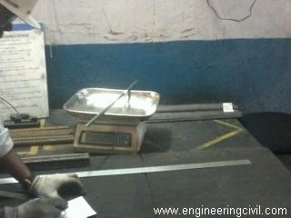
Fig : Weighting of rebar sample
For bars/wires whose pattern of deformation is such that by visual inspection, the cross-sectional area is substantially uniform along the length of the bar/wire, the effective cross-sectional area shall be the gross sectional area determined as follows, using a bar/wire not less than 0.5 m in length:
Gross cross-sectional area in mm2 = w/(0.00785 L)
where
w = mass weighted to a precision of + – 0.5 percent, in kg and
L = Length measured to precision of +-0.5 percent, in m
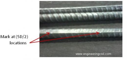
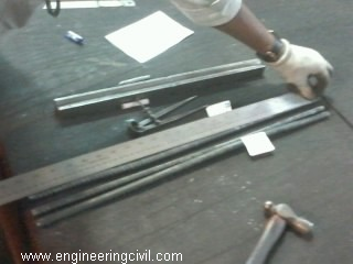
Fig : Measuring length of
Now the rebar sample is clamped in Universal testing machine (U.T.M) and
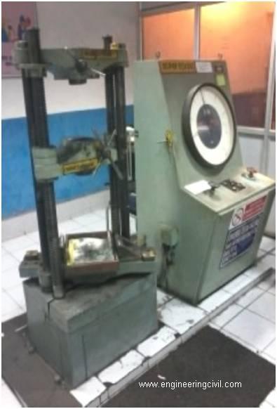
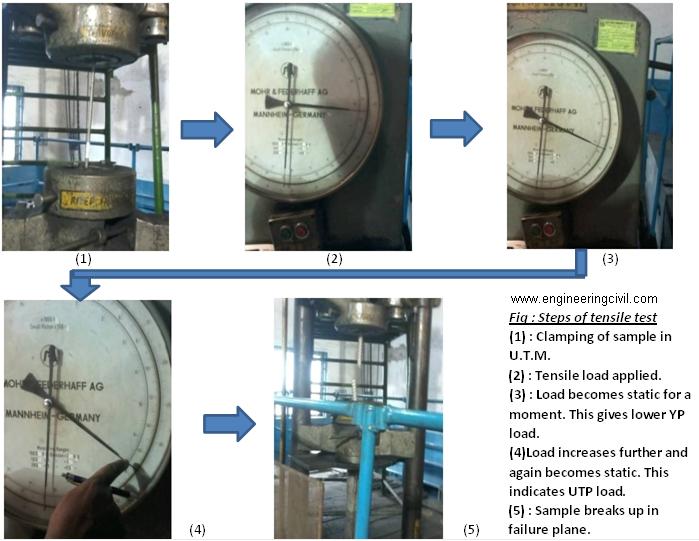
The load-deflection curve is as follows :
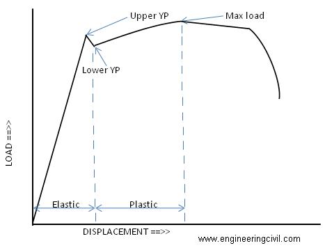
After plotting the above curve, we consider yield point YP = lower YP, in Newton (N).
Hence, yield stress YS = YP / A , in Mpa
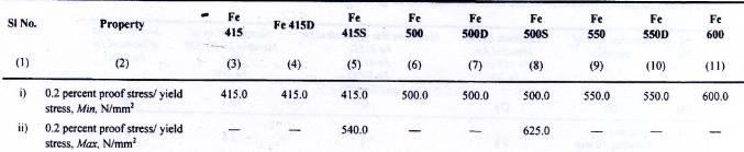
The value thus obtained must comply with 0.2 percent proof stress/yield stress as given in Table 3, sl. No. i and ii of IS 1786-2008 amend 1 given below:
From curve, ultimate tensile point UTP = Max load, in Newton (N).
Hence, ultimate tensile stress TS = UTP / A, in Mpa
The value thus obtained must comply with TS/YS ratio and minimum value of tensile strength as given in Table 3, sl. No. iii of IS 1786-2008 amend 1 as given below:
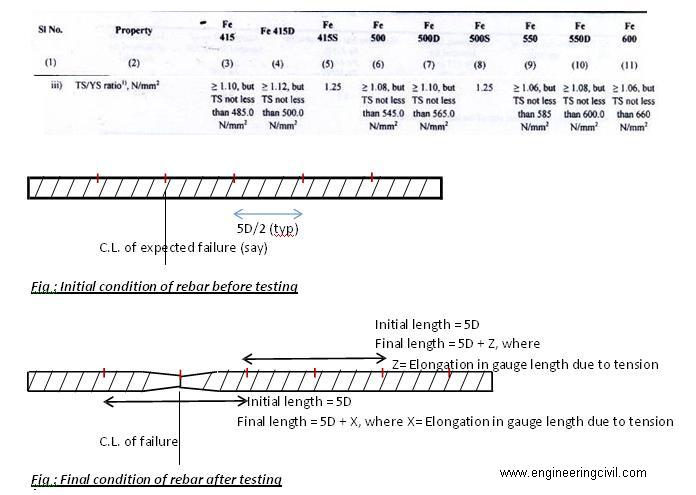
Consider final length = 5D + X between the marks adjacent to failure plane.
Therefore, % elongation = (Final length – Initial length)/Initial length x 100 %
i.e, X / 5D x 100 %
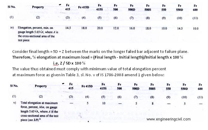
The value thus obtained must comply with minimum value of elongation percent as given in
Table 3, sl. No. iv of IS 1786-2008 amend 1 given below:
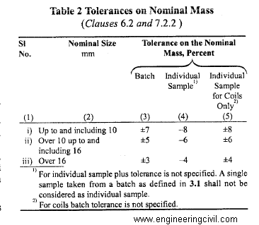
For a particular dia of rebar, we get the NOMINAL mass/m as given in table 1 of IS 1786-2008. MINIMUM mass/m can be obtained by calculating as per table 2 of IS 1786-2008.
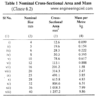
The ACTUAL mass/m = w/L must be within NOMINAL & MINIMUM values.
Thus conversely, weight tolerance may be calculated from NOMINAL & ACTUAL as:
= (NOMINAL – ACTUAL) / ACTUAL x 100 %
This value should be checked with the table 2 of IS1786-2008 given above.
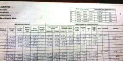
Fig : Typical register showing the test results
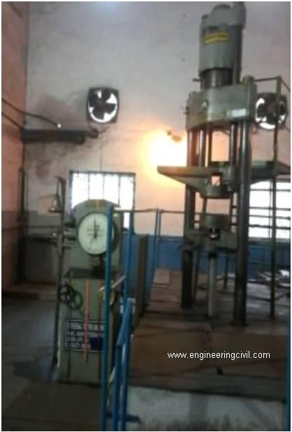
Bend test
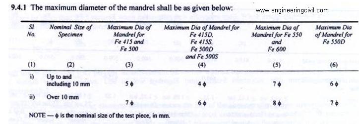
Bend test is being performed in 200 T capacity rebar bend testing machine, using mandrel of suitable sizes as per table 4 of IS1786-2008 amend 1 given below:
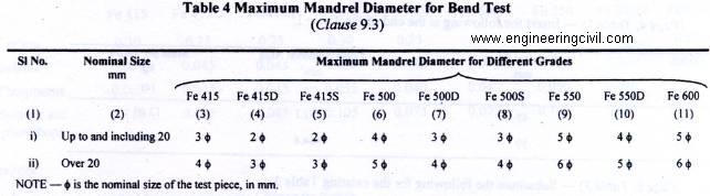
The bend test shall confirm to IS1599. The test piece should be bent over the mandrel by continuous pressure until the sides are parallel and forms an “U” shape.
The test sample shall be considered to be passed if no cracks or rupture are visible on
the bent portion.
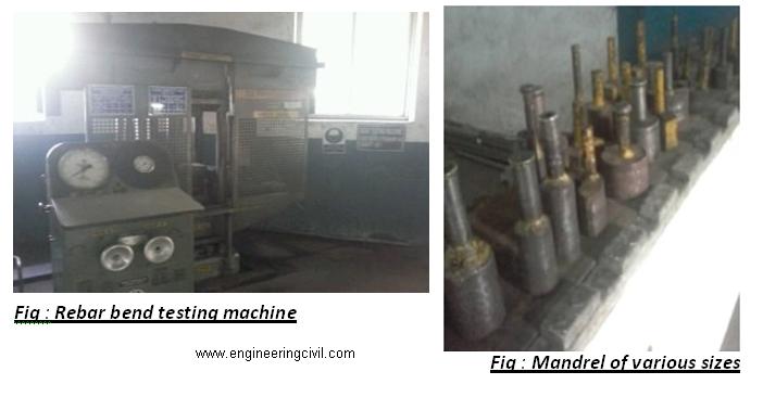
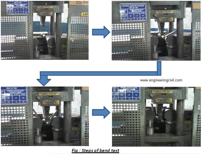
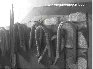
Fig : Bend pieces of rebar after test
Rebend test
The test piece shall be bent to an included angle of 135? in rebar bend testing machine,
using mandrel of suitable size as per Cl. 9.4.1 of IS1786-2008 amend 1 given below:
The bent piece is kept in boiling water for 30 minutes and then allowed to cool. The piece is now bent back to 157.5? in rebar bend testing machine.
The test sample shall be considered to be passed if no cracks or rupture are visible on the rebent portion.
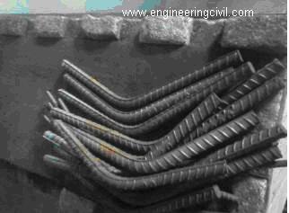
Fig : Bend pieces of rebar after rebend test
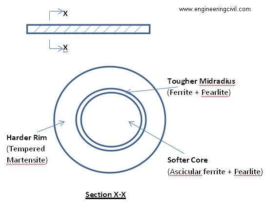
Microstructure test
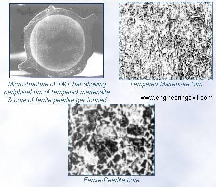
The typical TMT rebar section upon cutting will look like following:
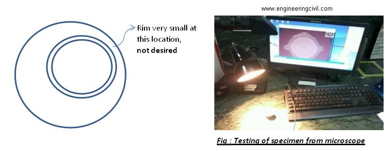
From the TMT rebar sample, a small piece is to be cut out and mirror finish to be done at its ends using grinding machine. Then rub with nital solution (2% nitric acid + ethyl alcohol). This technique is called ETCHING. Now a resinous coating is done on periphery of the specimen for easier handling.
The specimen is now kept under microscope and the dimensions of each layer, viz, core, midradius and rim are found out. It is desired that the tougher midradius and softer core should be at middle of the specimen, and not shifted unevenly, i.e, uniform rim is desired.
Now we need to determine the hardness of the specimen. Hence we perform Vicker’s hardness test.
Here the specimen is kept in Vicker’s testing machine and 10 to 30 Kgf load is applied, depending on the type of material, so as to get a small impression of the diamond pyramid indent on the TMT mirror finished surface. Henceforth measure the diagonal dimensions of the impression.
Now from table C.3 of IS 1501-2002, we can find out the hardness number corresponding to the value of test force and mean diagonal of indentation.
Thus we may find out the Vicker’s hardness number as xxxHVyy, where, xxx = Hardness number as per table C.3 of IS 1501-2002
HV = Hardness scale (Vickers)
yy = Load used in kgf
Typical xxx value for : Rim = 250 – 300
Core = 140-180
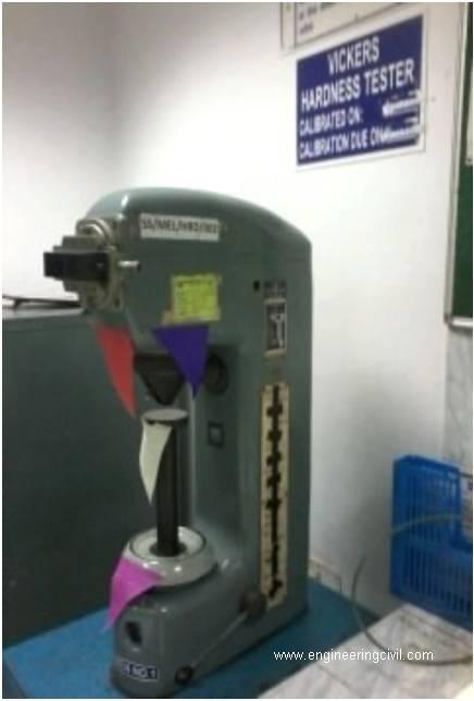
Fig : Vickers Hardness Tester
We at engineeringcivil.com are thankful to Sir Sourav Dutta for submitting this very useful information to us.
If you have a query, you can ask a question here.
Great source of tests information about rebar.
Thank’s Sir this is very good explanation
But i request you please provive details for tensilele strenth test of reinforced bar with total length and how to fit in the Utm machine at my mail Id