

By
KAUSHAL KISHORE
Materials Engineer, Roorkee
Fundamental principle
A pulse of longitudinal vibrations is produced by an electro-acoustical transducer, which is held in contact with one surface of the concrete under test. When the pulse generated is transmitted into the concrete from the transducer using a liquid coupling material such as grease or cellulose paste, it undergoes multiple reflections at the boundaries of the different material phases within the concrete. A complex system of stress waves develops, which include both longitudinal and shear waves, and propagates through the concrete. The first waves to reach the receiving transducer are the longitudinal waves, which are converted into an electrical signal by a second transducer. Electronic timing circuits enable the transit time T of the pulse to be measured.
Longitudinal pulse velocity (in km/s or m/s) is given by:
v=L/T
where
v = is the longitudinal pulse velocity,
L = is the path length,
T = is the time taken by the pulse to traverse that length.
EQUIPMENT FOR PULSE VELOCITY TEST
The equipment for ultrasonic pulse velocity measurement consists the following:
(i) Electrical pulse generator
(ii) Transducer-one pair
(iii) Amplifier
(iv) Electronic timing device
The natural frequency of transducers should preferably be within the range of 20 to 150 kHz (Table 1). Generally, high frequency transducers are preferably chosen for short path lengths and are more sensitive to detecting voids and low frequency transducers where the path length is longer.
Table 1 Natural Frequency of Transducers for Different Path Length (Ref.1)
| Path length (mm) | Natural frequency of transducer (kHz) | Min. transverse dimensions of members (mm) |
| Upto 500 | 150 | 25 |
| 500-700 | >= 60 | 70 |
| 700 – 1500 | > =40 | 150 |
| above 1500 | >= 20 | 300 |
The apparatus should be capable of measuring transit times to an accuracy of +/- 1 per cent over a range of 20 microseconds to 1 milliseconds.
There are three way of measuring pulse velocity through concrete (Fig. 1).
a) The direct method (cross probing) is preferred wherever access to opposite sides of the component is possible.
b)The semi-direct method is used whenever access to different but not opposite sides of the component is possible.
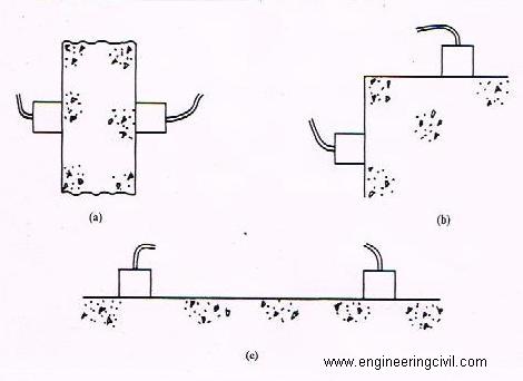
Fig.1 Types of Reading
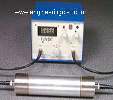
Fig.2 Ultrasonic Concrete Tester
c) The surface (indirect) method is the least satisfactory and should only be used when access to only one surface is possible. This method only indicates the quality of the concrete near the surface and is influenced by the presence of reinforcement parallel to the surface.
APPLICATIONS
The object of this method is basically to measure to velocity of pulses of longitudinal vibration passing through the concrete. These measurements may be used to establish:
(i) The homogeneity of the concrete
(ii) The presence of cracks, voids and other imperfections
(iii) Changes in the structure of the concrete which may occur with time
(iv) The quality of the concrete in relation to standard requirements
(v) The quality of one element of concrete in relation to another
(vi) The values of elastic modulus of the concrete
DETERMINATION OF PULSE VELOCITY
Where possible the direct transmission arrangement should be used since the transfer of energy between transducers is at its maximum and the accuracy of velocity determination is therefore governed principally by the accuracy of the path length measurement.
It is essential to make a good acoustical coupling between the concrete surface and the face of the transducer, and this is provided by a medium such as petroleum jelly, liquid soap or grease. Air pockets must be eliminated, and it is important that only a thin separating layer exists – any surplus must be squeezed out. A light medium, such as petroleum jelly or liquid soap, has been found to be the best for smooth surfaces, but a thicker grease is recommended for rougher surfaces which have not been cast against smooth shutters. If the surface is very rough or uneven, grinding or preparation with plaster of Paris or quick-setting mortar may be necessary to provide a smooth surface for transducer application. It is also important that readings are repeated by complete removal and re-application of transducers to obtain a minimum value for the transit time (T).
The path length (L) must also be measured to an accuracy of +-1%. This should present little difficulty with paths over about 500 mm, but for shorter paths it is recommended that calipers be used. The nominal member dimensions shown on drawings will seldom be adequate.
INFLUENCE OF TEST CONDITIONS
a) Moisture content
The moisture content has two effects on the pulse velocity, one chemical the other physical. These effects are important in the production of correlations for the estimation of concrete strength. Between a properly cured standard cube and a structural element made from the same concrete, there may be a significant pulse velocity difference. Much of the difference is accounted for by the effect of different curing conditions on the hydration of the cement while some of the difference is due to the presence of free water in the voids. It is important that these effects are carefully considered when estimating strength.
b) Influence of temperature of concrete.
The effect of temperature on pulse transmission is given below:
| Temperature | Correlation to the measured pulse velocity | |
| Air dried concrete | Water saturated concrete | |
| oC | % | % |
| 60 | +5 | +4 |
| 40 | +2 | +1.7 |
| 20 | 0 | 0 |
| 0 | -0.5 | -1 |
| -4 | -1.5 | -7.5 |
c) Influence of path length, shape and size of the concrete member
As concrete is inherently heterogeneous, it is essential that path lengths be sufficiently long so as to avoid any error introduced due to its heterogeneity. In field work, this does not pose any difficulty as the pulse velocity measurements are carried out on thick structural concrete members. However, in the laboratory where generally small specimens are used, the path length can affect the pulse velocity readings.
The shape and size of the concrete member do not influence the pulse velocity unless the least lateral dimension is less than a certain minimum value, for example the minimum lateral dimension of about 80 mm for 50 kHz natural frequency of the transducer.
d) Effect of reinforcing bars
The pulse velocity measured in reinforced concrete in the vicinity of reinforcing bars is usually higher than in plain concrete of the same composition. This is because, the pulse velocity in steel is 1.2 to 1.9 times the velocity in plain concrete and, under certain conditions, the first pulse to arrive at the receiving transducer travels partly in concrete and partly in steel.
The apparent increase in pulse velocity depends upon the proximity of the measurements to the reinforcing bar, the diameter and number of the bars and their orientation with respect to the path of propagation.
Table 2 Correction factors to allow for the effect of steel bars perpendicular to the direction of pulse propagation
| Ls/L | Velocity in concrete Vc km/s | ||
| Vc = 3.0 | Vc = 4.0 | Vc = 5.0 | |
| 0.10 | 0.95 | 0.96 | 0.98 |
| 0.15 | 0.93 | 0.95 | 0.97 |
| 0.20 | 0.90 | 0.93 | 0.96 |
| 0.25 | 0.88 | 0.92 | 0.95 |
| 0.30 | 0.85 | 0.90 | 0.95 |
L = total path length
Ls = total length of path through the steel.
INTERPRETATION OF RESULTS
The ultrasonic pulse velocity of concrete is mainly related to its density and modulus of elasticity. This in turn, depends upon the materials and mix proportions used in making concrete as well as the method of placing compaction and curing of concrete.
For example, if the concrete is not compacted as thoroughly as possible, or if there is segregation of concrete during placing or there are internal cracks or flaws, the pulse velocity will be lower although the same materials and mix proportions are used.
The assessment of compressive strength of concrete from ultrasonic pulse velocity values is not adequate. However if actual concrete materials and mix proportions adopted in a particular structure are available, then estimate of concrete strength can be made by establishing suitable correlation between the pulse velocity and the compressive strength of concrete specimens made with such materials and mix proportions, under environmental conditions similar to that in the structure. The estimated strength may vary from the actual strength by +20 percent. The correlation so obtained may not be applicable for concrete of another grade or made with different types of materials.
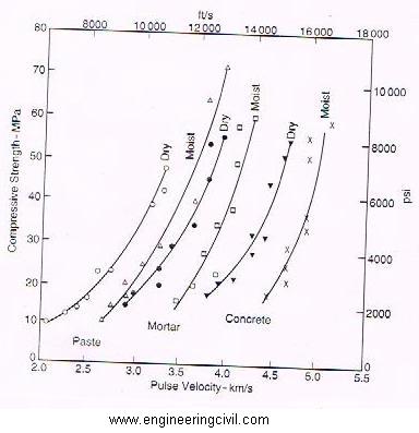
Fig.3 Relation between compressive strength and ultrasonic pulse velocity for hardened cement paste, mortar, and concrete, in a dry and moist condition (based on ref. 8)
Table 3 Pulse velocity ratings for concrete quality grading
| Quality | Pulse Velocity | ||
| After Malhotra6 km/sec | After Leslie and Chessman7km/sec | As per Bureau of Indian Standars1 km/sec | |
| Excellent | >4.6 | – | > 4.5 |
| Good | 3.7 to 4.6 | > 5.0 | 3.5 to 4.5 |
| Fair/Medium | 3.0 to 3.7 | 4.0 to 5.0 | 3.0 to 3.5 |
| Poor | 2.1 to 3.0 | 3.0 to 4.0 | <3.0** |
| Very poor | <2.1 | – | – |
** In case of ultrasonic pulse velocity less than 3.0 km/sec, concrete is designated as “Doubtful” and it may be necessary to carry out further tests.
CONCLUSION
Ultrasonic pulse velocity measurement has been found to be a valuable and reliable method of examining the interior of a body of concrete in a truly non-destructive manner. It is essential that test results are properly evaluated and interpreted by expert who are familiar with the technique. It is better if similar concrete at the same time be tested with one more non-destructive test method, such as concrete test hammer etc. for conclusive results.
REFERENCES
1. IS: 13311 (Part 1): 1992, Non-destructive testing of concrete Methods of test, part 1 Ultrasonic Pulse Velocity, BIS, New Delhi.
2. BS: 4408 :Part 5: 1974 , Measurement of the velocity of ultrasonic pulse in concrete, British Standards Institution, London.
3. IRC Highway Research Board New Delhi 1996, Special Report-17, Stare of the art: Non-destructive testing technique of concrete bridges.
4. A.M. Neville, Properties of Concrete, 4th Edition.
5. J.H. Bungey, S.G. Millard, M.G. Grantham, Testing of Concrete in Structures.
6. Malhotra, V.M., Testing hardened concrete : Non-destructive methods, ACI Monograph No. 9, 1976.
7. Leslie, J.R. and Cheesman, W.J., An ultrasonic Method of Studying deterioration and cracking of concrete structures, Journal of ACI, Proceeding, Vol. 46, No. 1, September 1949, pp. 17-36.
8. V.R. Sturrup, F.J. Vecchio and H. Caratin, Pulse velocity as a measure of concrete compressive strength in situ/Non-destructive testing of concrete, Ed. V.M. Malhotra, ACI SP-82 pp. 201-27 (Deteroit, Michigan, 1984).
9. International Atomic Energy Agency, Vienna – 2002, Training course series No. 17, Guide book on non-destructive testing of Concrete Structures, pp. 100-127.
We at engineeringcivil.com are thankful to Sir Kaushal Kishore for submitting this very useful paper on “ULTRASONIC TESTING OF CONCRETE” to us. We are hopeful that this will be of great use to all those who wish to learn more about the Non-destructive testing of concrete.
If you have a query, you can ask a question here.
Please advice to me this test is related to COLD JOINTS & core test maximum depth as per IS Code
always update me on how to carry out ndt test on structures
Hi,
When the testing of concrete by ultrasonic velocity, used a indirect method while opp face are not accessible. During analysis amd time of reporting why correction are applied in only indirec mathod. Few report i obseved that, tjey applied a +1km/sec after result in only indir. Method.
So , i kindly clear that reason behind of it.