

By
Prof. Amol B. Kawade, Miss.Shruti P. Meghe
Amrutvahini College of Engineering, Sangamner
Abstract
Several crossings with a variety of different conditions under which a Submerged Floating Tunnel, SFT or Archimedes Bridge, may be used. However, swell, vortex shedding and slowly varying internal waves due to layers of different salinity presented a hazard of significant dynamic oscillations. In addition to the challenge of these various conditions some common accidental situations have to be solved for all applications including fire, sinking ships, falling anchors as well as sudden massive water ingress into the tube. Combining with the characteristics of submerged floating tunnel (SFT) and surrounding environment, it is of great theoretical and practical significance to develop research in the areas of potential risk and impact factors, risk index system, risk level of SFT. Risk management workflow of SFT was given. Then we focused on discussing the potential risks of SFT in investment, design, and environmental condition during planning and feasibility study stage.
Some measures and suggestions in risk control strategy were given. Based on the design technology of immersed tunnel, bridge and tunnel engineering, combining the current relevant design codes segment is presented according to safety, applicability, economy, fine appearance and environmental protection. The selection of tube cross section type, structural analysis, design load, waterproofing and resistant corrosion, tube joint design and tunnel ventilation of submerged floating tunnel etc are described and explored by comprehensively considering the design load, flow resistance performance, durability and other factors of submerged floating tunnel.
1. INTRODUCTION
1.1 HISTORY
The first underwater tunnel was build over four thousand years ago, but floating tunnels are much more recent. Certainly an engineer and builder of railways, S. Préault , proposed but did not build an SFT across the Bosphorus in 1860, an elegant underwater railway viaduct with spans of about 150 m founded on piers, located some 20 m below the surface. Per Hall proposed a deeper SFT for the Bosphorus in 1976, but by 1977 his proposal had become a buried immersed tunnel for environmental reasons (fish habitat). An immersed tunnel is now in place beneath the Bosphorus awaiting the last of the TBMs to reach it. Going back now to 1882, Edward Reed proposed a submerged railway tunnel across the English Channel supported on caissons, but Parliament in England rejected it for fear of invasion. It was patented and since then, many other patents have been taken out for SFT, including some in the UK, USA, Norway, Sweden and Italy. Once the first immersed tunnel had been successfully built in 1893, the way was open also for constructing SFT – initially at least those that would be pier supported. Since 1923 [3], the potential of an SFT has been recognized in Norway as a way to create a practical castal highway across fjords that would otherwise be too deep even for bored tunnels to make sense; some of the existing bored tunnel connections even with 10% grades are very, very long. This need for shorter shallower tunnels for a number of fjord crossings has led to detailed investigations and field tests that still continue today. The most wellknown crossing evaluated in some detail in Norway is for Hogsfjord , but the SFT was abandoned for local political reasons. Private investors have examined a number of other locations. Another serious contender is the Sula-Hareld crossing. The first of a series of Strait Crossing Symposia in Norway began in 1986 (the fifth was in 2009) in which SFT have played an increasingly greater part.
1.2 GENERAL
Tunnels in water are by no means new in civil engineering. Since about 1900, more than 100 immersed tunnels have been constructed. Bridges are the most common structures used for crossing water bodies. In some cases immersed tunnels also used which run beneath the sea or river bed. But when the bed is too rocky , too deep or too undulating submerged floating tunnels are used .
The Submerged Floating Tunnel concept was first conceived at the beginning of the century, but no actual project was undertaken until recently. As the needs of society for regional growth and the protection of the environment have assumed increased importance, in this wider context the submerged floating tunnel offers new opportunities. The submerged floating tunnel is an innovative concept for crossing waterways, utilizing the law of buoyancy to support the structure at a moderate and convenient depth .The Submerged floating Tunnel is a tube like structure made of Steel and Concrete utilizing the law of buoyancy .It supported on columns or held in place by tethers attached to the sea floor or by pontoons floating on the surface. The Submerged floating tunnel utilizes lakes and waterways to carry traffic under water and on to the other side, where it can be conveniently linked to the rural network or to the underground infrastructure of modern cities.
1.3 REASON FOR CHOOSING FLOATING TUNNEL
Floating tunnel is the totally new concept and never used before even for very small length. It can be observed that the depth of bed varies from place to place on a great extent. The maximum depth is up to 8 km. also at certain sections. The average depth is 3.3 km. The two alternatives are available for constructions are bridge above water level or tunnel below ground level. Since the depth is up to 8 km it is impossible to construct concrete columns of such height for a bridge. And also the pressure below 8km from sea surface is nearly about 500 times than atmospheric pressure so one cannot survive in such a high pressure zone. So the immersed tunnels also cannot be used. Therefore, floating tunnel is finalised which is at a depth 30m from the sea level, where there is no problem of high pressure. This is sufficient for any big ship to pass over it without any obstruction.
1.4 BASIC PRINCIPLE OF SFT
SFT is a buoyant structure which moves in water. The relation between buoyancy and self weight is very important, since it controls the static behaviour f the tunnel and to some extend, also the response to dynamic forces. Minimum internal dimension often result in a near optimum design. There are two ways in which SFT can be floated. That is positive and negative buoyancy.
Positive buoyancy: In this the SFT is fixed in position by anchoring either by means of tension legs to the bottom or by means of pontoons on the surface. Here SFT is mainly 30 metres below the water surface.
Negative buoyancy: Here the foundations would be piers or columns to the sea or lake. This method is limited to 100 meters water depth
SFT is subjected to all environmental actions typical in the water environment: wave ,current , vibration of water level, earthquake, corrosion, ice and marine growth. It should be designed to with stand all actions, operational and accidental loads, with enough strength and stiffness. Transverse stiffness is provided by bottom anchoring.
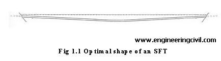
1.5 OPTIMAL SHAPE OF SFT
The shape of the SFT in Fig. 1 has been chosen for the following reasons: When the vertical curvature is concentrated in the middle of the SFT, it is easier to shorten the concrete tube during installation, variations in the buoyancy in the middle of the tunnel introduce little bending in the tunnel. Similarly an unusual amount of water in the middle of the tunnel gives little bending and axial force.
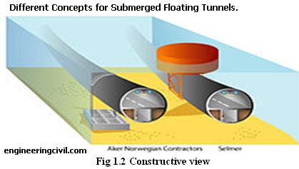
1.6 CONSTRUCTION
The concept of submerged floating tunnels is based on well-known technology applied to floating bridges and offshore structures, but the construction is mostly similar to that of immersed tunnels: One way is to build the tube in sections in a dry dock; then float these to the construction site and sink them into place, while sealed; and, when the sections are fixed to each other, the seals are broken. Another possibility is to build the sections unsealed, and after welding them together, pump the water out. The ballast used is calculated so that the structure has approximate hydrostatic equilibrium (that is, the tunnel is roughly the same overall density as water), whereas immersed tube tunnels are ballasted more to weight them down to the sea bed. This, of course, means that a submerged floating tunnel must be anchored to the ground or to the water surface to keep it in place (which of these depends on which side of the equilibrium point the tunnel is).
1.7 DESIGN PRINCIPLE AND PROCESS OF SFT TUBE
SFT tube provides space for traffic and buoyancy for carrying different dead and live loads. The design of SFT tube relates to oneself safety and applicability. The design load, buoyancy to weight ratio, flow resistance performance, durable performance and other factors are considered comprehensively during the tube design process. By alternatives comparison from technique, economy and environmental protection, the optimal plan should extremely utilize the space to satisfy the traffic headroom and meet the demand of ventilation and escape according to the requirements of safety applicability, reliable quality, economical rationality and advanced technology.
The principles of tube design are as follows:
• The buoyancy to weight ratio is less than 1.0, related researches show that the ratio should be between 0.5 an0.8.
• Tube should meet the demand of strength, stiffness and stability during construction and operation stages.
• The variation of surface curvature should be gentle to resist the hydrodynamic. Meet the standard for classification of seismic protection of buildings.
2. STRUCTURAL COMPONENTS OF SFT
Submerged floating tunnel consists of many structural components. These components should provide strength and stiffness against the various forces acting under the water surface.
The three basic structural components are:
• Tube
• Anchoring
• Shore connections
2.1 Tube: It should accommodate the traffic lanes and the equipment. External shape can be circular , elliptical or polygonal. It may be constructed of steel or concrete. Corrosion protection is the main issue. Tube is composed of elements of length varying from one hundred meters to half a kilometre.
2.2 Anchoring:
There are basically four types of anchoring:
• SFT with pontoons
• SFT supported on columns
• SFT with tethers to the bottom
• SFT unanchored
2.2.1 SFT with pontoons: It is independent of water depth, the system is sensitive to wind, waves, currents and possible ships collision. Design should be such that if one pontoon is lost, then also the structure will survive.
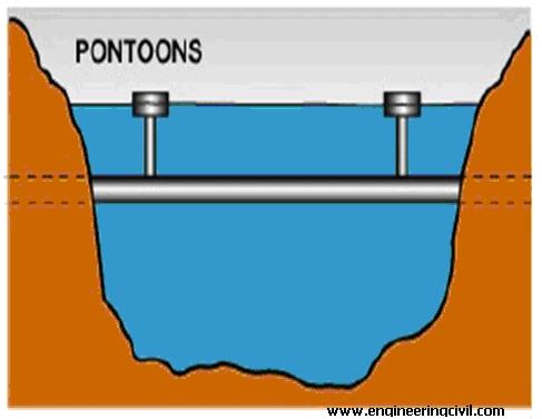
Fig. 2.1. SFT with pontoons
2.2.2 SFT supported on columns: It is an “underwater bridge” with foundations on the bottom, in principle the columns are in compression but they may also be a tension type alternative. Water depth will play an important role in this case and a few hundred meters depth is considered a limit at the present time. However, much deeper foundations are at present under investigation.
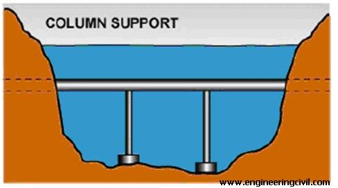
Fig 2.2 SFT supported on columns
2.2.3 SFT with tethers to the bottom : It is based on tethers being in tension in all future situations, no slack in these tethers may be accepted in any future load cases. The present practical depths for this type of crossing may be several hundred meters, whether the tethers are vertical or a combination of vertical and inclined.
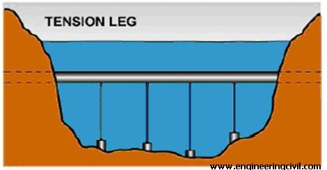
Fig. 2.3 SFT with tethers to the bottom
2.2.4. SFT unanchored: It is interesting as it has no anchoring at all except at landfalls and is then independent of depth. There is obviously a limit to the length but only further development will answer this. Perhaps an alternative for light traffic should be designed, possibly a 100 or 200 meter long.
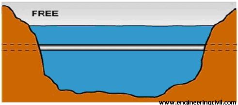
Fig. 2.4 SFT unanchored
2.3 Connection:
The connections of the tube to the shore require appropriate interface elements to couple the flexible water tube with the much more rigid tunnel bored in the ground. This joint should be able to restrain tube movements, without any unsustainable increase in stresses. On the other hand , the joints must be water tight to be able to prevent entry of water. Additional care in shore connections is required, especially in seismic areas , due to the risk of submarine landslides
2.4 Structural design of SFT tube:
SFT tube keeps balance under the action of buoyancy and cable tension bears vehicle load, wave-current load, temperature load and so on. In the system transformation during prefabrication, floating, installation and operation, the stress of tube is complex, so the tube design should carry on longitudinal and transverse analysis under these working conditions.
SFT tube load is divides into permanent load, variable load and accidental load. The permanent includes structure weight, buoyancy, hydrostatic pressure, concrete shrinkage etc.
The variable load includes vehicle load, water head load, wave-current load, temperate load, construction load etc. The accidental load includes seismic, sunken ship load, blast load, leakage etc.
SFT tube is designed under ultimate limit state and serviceability limit state just as traditional hydraulic structure design [1], moreover, the stress and displacement should be analyzed and checked under progressive damage Limit state and fatigue limit state based on structural reliability theory.
2.5 Tube joint design
Joint design of SFT tube should conform to four principles:
• Not seepage in construction and operation stage, reliable water tightness and durability. Concise design, stressing definite and working independently.
• Transferring construction load effectively in construction stage and convenient construction.
• Transferring stress and deformation effectively in construction stage, fine seismic performance.
• There are two ways of tube joint based on stiffness and deformation: rigid joint and flexible joint.
2.6 Waterproofing and corrosion protection design of SFT tube
Tube ventilation design is an important link of SFT design, and quality of ventilation scheme and operation effect has direct relation to engineering cost, operation environment, disaster-relieving function and operation benefit. The aim of tube ventilation is to guarantee allowable concentration of harmful gas represented by carbon monoxide, provide healthy environment and suitable visibility for people and vehicle in tunnel, and control pervasion of smog and heat for evacuation and extinguishment when fire occurs.
Tube ventilation should accord with following requirements
• Design wind speed of one-way traffic tunnel is not more than 10m/s; design wind speed of two-way traffic tunnel is not more than 8m/s.
• Noise produced by ventilation fan and exhaust emission meet the environment protection guidance.
• Ventilation type is stable when the transportation condition changes or fire occurs. Downstream direction of operation ventilation is stable.
3. COMPETITIVE FEATURES OF SFT
3.1 Invisible
Crossing waterways, whether being from main land to islands in the sea or maybe more important crossing an inland lake, perhaps the one we are at now will in many cases meet protests both from tourist interests and also from the public in general. Lakes of special beauty or perhaps historical value should be preserved for the future, the crossing of such areas and lakes with SFT may make this possible. An illustration of this may be seen in Fig. 3.1
3.2. Length only from shore to shore
The actual SFT structure is only as long as the distance between the shores. If desired the SFT may be connected directly to tunnels and then be completely out of sight for any desired distance.
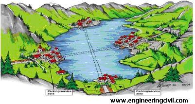
Fig. 3.1.SFT crossing of lakes
3.3. Very low gradient
Crossings with undersea tunnels or bridges will frequently mean longer structures with consequently higher costs and this may offset the higher cost per meter for an alternative SFT. An SFT crossing may have a very gentle gradient or being nearly horizontal giving considerable savings in energy used by traffic.
3.4. Access to underground service-parking space at ends
As the SFT may continue in tunnels having crossed the waterway, it is possible to arrange parking places or service areas under ground and provide access to the surface by lifts directly into cities or recreational areas as shown in Fig. 3.2. These possibilities may be one of big advantages in future, in fact for all types of tunnels.
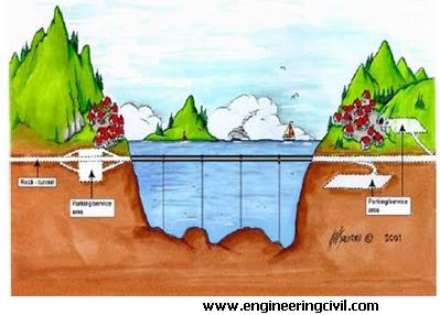
Fig.3.2. Parking and service areas
3.5. May surface just above shoreline
As an SFT may be positioned at any depth below the surface arrangements may be made that the SFT surfaces at or very near the shoreline. This may be an advantage for connections to new or existing road systems and gives the planners freedom to locate connections in a very flexible way.
3.6. Constructed away from densely populated areas
Construction of infrastructure is a major everyday problem in many cities, traffic is piling up, new one way streets daily and generally great frustrations by millions of people. One very interesting feature with SFT is that the actual construction may be done away from the densely or highly populated areas, a feature also for immersed tunnel construction. After the sections of the tunnel are finished they may be towed to the actual site and there joined together and installed at the desired depth. In some instances the whole length of the SFT may be assembled at the construction site and the complete structure towed to the actual site and installed. This would ensure minimum disturbances to the local area and perhaps the whole operation may only take months instead of years.
3.7. Easy removal at end of life
All structures will have to be removed or replaced sooner or later and as the amount of structures increase it is important to prepare for these operations already at the planning and design stage. Removal, recycling or reuse of materials or parts of the structures will become increasingly necessary in the future, for both economic and environmental reasons. SFT is in most cases a floating structure as a whole and may therefore be towed away to some place where parts of the SFT may be reused. One may imagine such an operation by for instance placing bulkheads in the original elements and then separating the SFT in suitable lengths to be perhaps towed to different locations for reuse or destruction.
3.8. Some possibilities of reuse or recycling SFT
Sections of a tunnel may be used for many purposes, depending on its size and condition. One obvious possibility is for various types of storage facilities, whether in the sea or on dry land, a section of tunnel ,say 12 meters in diameter cut to a length of 10 to 15 meters would not present any difficulty to get up on dry land if that was desired. To cut a concrete tunnel into sections would not present big difficulties either; it’s more a question of overall economy than technology.
4. CONCLUSION
The submerged floating tunnel will set up new trends in transportation engineering and which shows with the advances in technology that will reduce the time required for travelling. And make the transportation more effective by hiding the traffic under water by which the beauty of landscape is maintained and valuable land is available for other purposes. Benefits can be obtained with respect to less energy consumption, air pollution and reduced noise emission. For wide and deep crossings the submerged floating tunnel may be the only feasible fix link, replacing present day ferries and providing local communities with new opportunities for improved communication and regional development.
REFERENCES
1. Christian Ingerslev “Immersed and floating tunnels” Science Direct VOL. 4 ,2010 PP:51-59.
2. Keqian Zhanga, Yiqiang Xianga,*, Yinguang Dub “Research on tubular segment design of submerged floating tunnel” Science Direct VOL. 4,2010 .PP:195-205.
3. Yiqiang Xiang*, Chengxi Liu, Keqian Zhang, Qiangqiang “Risk analysis and management of submerged floating tunnel and its applications” Science Direct VOL. 4,2010,PP:107-116.
4. Bernt Jakobsen “Design of the Submerged Floating Tunnel operating under various conditions” Science Direct VOL. 4 2010 ,PP:71-79.
5. Fei Ge*, Wei Lu, Xiaodong Wu, Youshi Hong “Fluid-structure interaction of submerged floating tunnelin wave field” Science Direct Vol 4 2010 PP:263-271.
6. Jian Xiao, Guojun Huang “Transverse earthquake response and design analysis of submerged floating tunnels with various shore connections” Science Direct Vol 4 2010
PP: 233-242.
We at engineeringcivil.com are thankful to Prof. Amol B. Kawade and Miss.Shruti P. Meghe for submitting their research paper on “Submerged Floating Tunnel” to us. We are sure this will be of great help to all those who are looking for more information on Submerged Floating Tunnels.
If you have a query, you can ask a question here.
What is major structural construction problem of Floating Tunnel ?