

By
Singh P.K. (Department of Civil Engineering, National Institute of Technology, Kurukshetra, Haryana, INDIA)
Arora V.K. Professor, (Department of Civil Engineering, National Institute of Technology, Kurukshetra, Haryana, INDIA)
Abstract
Steel pipe piles are highly durable, provide reliable foundation, have shorter construction period and can be driven into such medium where other piles can’t like boulder medium. Steel pipe piles are economical for long piles into deeps loose soil. Till now most of research has been directed towards the response of individual piles to vertical loads. Both the driving response and static bearing capacity of open-ended piles are affected by the soil plug that forms inside the pile during pile driving. In order to investigate the effect of the soil plug on the static and dynamic response of an open-ended pile and the load capacity of pipe piles in general, field pile load tests were performed on instrumented open- and closed-ended piles driven into sand. For the open-ended pile, the soil plug length was continuously measured during pile driving, allowing calculation of the incremental filling ratio for the pile.
Keywords- Pile Foundation, pile cap, bearing capacity, pile group, pile load tests, piles driving
Introduction
Pile foundations have been used as load carrying and load transferring systems for many years. Pile foundations are the part of a structure used to carry and transfer the load of the structure to the bearing ground located at some depth below ground surface. The main components of the foundation are the pile cap and the piles. Pipe piles can be either open-ended or close-ended. It has been documented that the behavior of open-ended piles is different from that of closed-ended piles. At the earlier time, the capacity of pile groups was taken as equal to the sum of the capacities of the individual piles. However, in practice, when piles are placed close to each other, the stresses transmitted to the soil through neighboring piles will overlaps, resulting in a considerable change of the group capacity [1, 2].
According to the field test results of Szechy (1959), the blow count necessary for driving a pile to a certain depth in sands is lower for an open-ended pile than for a closed-ended pile. Thus, it is generally acknowledged that an open-ended pile requires less installation effort than a closed-ended pile under the same soil conditions. [1]
However, other research results McCammon and Golder (1970), Lu (1985), Smith et al. (1986); Brucy et al. (1991) have shown that the mode of pile driving is an important factor in driving resistance. If a pile is driven in a fully coring or fully unplugged mode, soil enters the pile at the same rate as it advances. On the other hand, if a pile is driven under plugged or partially plugged conditions, a soil plug finally attaches itself to the inner surface of the pile, preventing additional soil from entering the pile.
It is known that a short open-ended pile has lower load capacity than an equivalent closed-ended pile. However, as pile length or penetration depth increases, the load capacity of the open ended pile approaches that of the equivalent closed-ended pile.
This is due to the greater degree of soil plugging with larger penetration depth Klos and Tejchman (1981), Paikowsky and Whitman (1990). According to Szechy (1961), the settlement of an open-ended pile is greater than that of a closed-ended pile under the same load and soil conditions. [1][2]
However, the difference in load capacities varies within a wide range, depending on the degree of soil plugging during driving.
Material and Methodology
The research work was divided into different headings as determination of index properties of loose sands, procurement of pile cap material, steel piles, sand etc, preparation of test model, testing of pile and pile groups and finally evaluation and comparison of test results.
Material
Sand: The sand used in the investigations has been collected from the banks of river Yamuna from a village near Radaur in Yamunanagar district of Haryana. The physical and engineering properties of Yamuna sand have been summarized in table below.
TABLE 1.0 PROPERTIES OF YAMUNA SAND
| S. No. | Property | Value |
|
1. |
Effective size (D10) | 0.139mm |
|
2. |
Uniformity coefficient (Cu) | 2.06 |
|
3. |
Coefficient of curvature (Cc) | 0.982 |
|
4. |
IS Classification | SP |
|
5. |
Passing 1.18 mm IS Sieve | 100% |
|
6. |
Mean specific gravity (G) | 2.64 |
|
7. |
Minimum void ratio emin /max. dry density | 0.54/1.690 gm/cc |
|
8. |
Maximum void ratio emax/min. dry density | 0.77/1.472 gm/cc |
Steel pile: It is usually desirable from economical and practical considerations that the smallest model should be used. At the same time the model pile should be slender and also wide enough so that the effect of individual soil grains is negligible. The piles were used having 2 cm diameter and the total length of pile was 50 cm with an embedded length of 40 cm.
Mild steel plates: Mild Steel Plates can come in various sizes and grades. Thicknesses available range from 3mm up to as thick as 150mm. The plate used in making of pile caps is of 12 mm thickness which is cut according to the required dimension of pile caps.
The spacing between the piles in each group was 2.5 times of pile diameter. The size of pile cap varied according to the number of piles in a group. A minimum cover of approximately half the pile spacing was provided around the outer piles. The length of embedment of piles was kept as 40 cm in all the tests. Total thirteen tests were performed in which five circular groups were also tested. The details of the pile groups are shown in the Appendix A.
Test Procedure
Single Pile Testing
The single pile was driven into the sand. The proving ring was attached to the lower end of screw jack. Two dial gauges were fixed at the top of pile cap. These Baty dial gauges (least count 0.01 mm and 25 mm travel) were supported on a cross angle sections through magnetic bases. The average of dial gauge readings was taken as the average settlement under a particular load.
The load was applied in small increments. Load was maintained constant after an increment, till the settlement was constant. When there was no movement of dial gauge readings were recorded. Next increment was applied and the process was repeated till failure i.e. when the pile started setting rapidly. Graph below shows the load-settlement curve obtained from the Appendix B.
Pile Group Testing [3]
The proving ring was attached to the screw jack. Two dial gauges were suitably mounted on the pile cap at opposite corners. It was checked by tapping that the dial gauges were securely fixed. The load is than applied at the centre of pile cap by turning the screw jack. After each increment, the load was maintained constant till the settlement was constant.
After the settlement was complete, the next increment of load was applied and the process continued till the pile group started sinking. From the recorded readings of proving ring and dial gauges, the values of load settlement were computed. The load settlement curves obtained for various pile groups are shown in Appendix B.
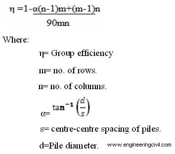
Theoretical Pile Group Efficiency
The efficiency of pile groups were calculated by using the pile group efficiency equation. There are many pile group equations. These equations are to be used very cautiously, and may in many cases be no better than a good guess. The Converse-Labarre Formula is one of the most widely used group-efficiency equations which is expressed as
Experimental Pile Group Efficiency
The spacing of piles is usually predetermined by practical and economical considerations. The design of a pile foundation subjected to vertical loads consists of
1. The determination of the ultimate load bearing capacity of the group Qgu.
2, Determination of the settlement of the group, Sg , under an allowable load Qga.
Test Result and Interpretation
The data obtained from tests on open end pile groups and closed end pile groups at various spacing’s is presented and interpreted in the following sections.
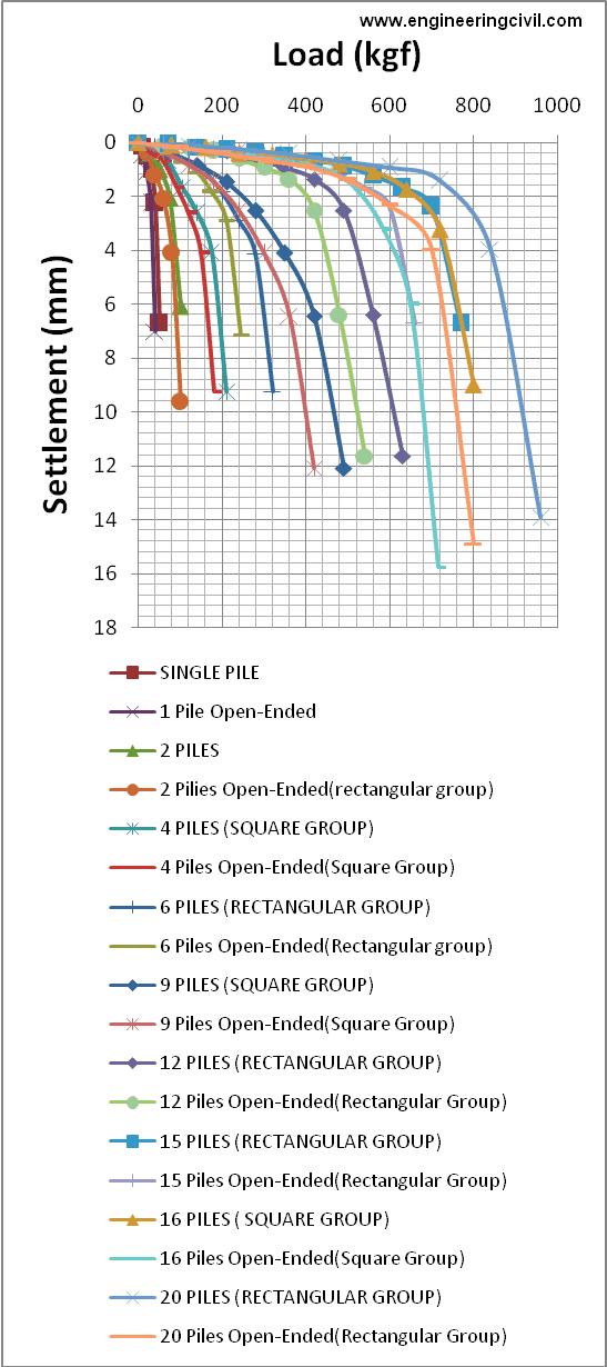
Failure load
The load settlement plot obtained for the open ended and closed ended pile groups are shown below. A glance of this figure indicates that load settlement plot approaches almost vertical tangent when the pile start sinking rapidly. The load corresponding to rapid sinking of the pile is taken as the failure load of the pile. The failure loads for the pile groups have been obtained in the similar manner.
Comparison of Experimental Failure Load with Other Theories
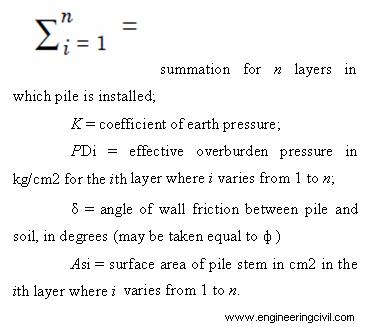
The ultimate bearing capacity (Qu) of piles in granular soils is given by the following formula:
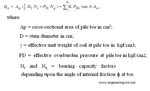
NOTE 1 — Nr factor can be taken for general shear failure as per IS: 6403-1981*.
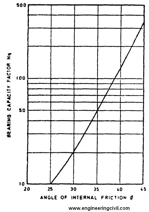
NOTE 2 — Nq factor will depend, apart from nature of soil on the type of pile and its method of construction, for bored piles, the value of Nq corresponding to angle of shearing resistance are given in Fig. 1. This is based on Berezantseu’s curve for D/B of 20 up to = 35° and Vesic’s curves beyond = 35°.
NOTE 3 — the earth pressure coefficient K depends on the nature of soil strata, type of pile and its method of construction. For bored piles in loose medium sands, K values between 1 and 3 should be used.
NOTE 4 — the angle of wall friction may be taken equal to angle of shear resistance of soil.
NOTE 5 — in working out pile capacities using static formula, for piles longer than 15 to 20 pile diameter, maximum effective overburden at the pile tip should correspond to pile length equal to 15 to 20 diameters.
TABLE 2.0 PLOT FOR BEARING CAPACITY FACTOR VS ANGLE OF INTERNAL FRICTION
Conclusion
From the model tests carried out on vertical pile groups of rectangular, square and circular in loose sand following conclusion have been drawn:-
1. The pile group load increases as number of piles in a group are increased.
2. The efficiency of driven pile groups in sand is maximum in square group and lesser in rectangular group.
3. The experimental efficiency of pile groups is more than the efficiency obtained by converse-Labarre formula.
4. The efficiency obtained by the experiment in loose sand is more than 1.
5. The ultimate bearing capacity of circular groups is more in comparison of other two groups.
6. The experimental failure loads for pile groups are higher than the failure loads obtained using I.S code method.
APPENDIX-A
The details of pile groups are shown below.
WEIGHT OF PILE GROUPS
| S.No |
Pile Group |
Types |
No. of Piles |
Weight (kg) |
|
1. |
—— |
Square |
1 |
0.331 |
|
2. |
1X1 |
Rectangular |
2 |
0.735 |
|
3. |
—— |
Circular |
3 |
1.08 |
|
4. |
2X2 |
Square |
4 |
1.07 |
|
5. |
—— |
Circular |
5 |
1.70 |
|
6. |
2X3 |
Rectangular |
6 |
1.57 |
|
7. |
—— |
Circular |
7 |
2.31 |
|
8. |
3X3 |
Square |
9 |
2.23 |
|
9. |
—— |
Circular |
11 |
2.71 |
|
10. |
3X4 |
Rectangular |
12 |
2.99 |
|
11. |
3X5 |
Rectangular |
15 |
3.77 |
|
12. |
4X4 |
Square |
16 |
3.92 |
|
13 |
4X5 |
Rectangular |
20 |
4.90 |
|
S.NO |
Pile Group |
No. of Piles |
Ultimate Bearing Capacity Open-Ended Piles (kgf) |
Ultimate Bearing Capacity Closed- Ended Piles
(kgf) |
|
1. |
— |
1 |
29.84 |
40.33 |
|
2. |
1X1 |
2 |
67.41 |
90.735 |
|
3. |
2X2 |
4 |
130.305 |
176.088 |
|
4. |
2X3 |
6 |
195.37 |
266.57 |
|
5. |
3X3 |
9 |
297.65 |
402.23 |
|
6. |
3X4 |
12 |
365.79 |
492.99 |
|
7. |
3X5 |
15 |
477.90 |
653.77 |
|
8. |
4X4 |
16 |
539.90 |
718.92 |
|
9. |
4X5 |
20 |
642.124 |
844.90 |
APPENDIX –B ULTIMATE BEARING CAPACITY OF OPEN-ENDED AND CLOSED ENDED PILE GROUPS
FIG 1.0 COMPARISON OF SINGLE CLOSED AND OPEN ENDED PILE

FIG 2.0 LOAD SETTLEMENT CURVES OF ALL GROUPS
References
[1] Kyuho Paik; Rodrigo Salgado; Junhwan Lee; and Bumjoo Kim. Behavior of Open- and Closed-Ended Piles Driven Into Sands.
[2] Meyerhof, G.G., 1959. Compaction of sands & Bearing capacity of piles. JSMFD, ASCE, 85, SM 6, 1-29.
[3] IS: 1498 (1970), “Indian Standard Methods of Test for Soils: Classification and Identification of Soil for General Engineering Purposes”, Bureau of Indian Standards.
We at engineeringcivil.com are thankful to Mr Priyank Kumar Singh for submitting this reaseach paper on “Behaviour of Open and Closed End Pile Groups Subjected To Vertical Loading : A Comparative Study” to us. We are hopeful that this will of great use to all those seeking more information on open and closed end piles.
If you have a query, you can ask a question here.